Coupling fixed bed oxygen-enriched continuous gasification process

A fixed-bed, coupled technology, applied in the petroleum industry, combined combustion mitigation, manufacturing of combustible gas, etc., can solve the problems of sensible heat loss, low utilization rate of raw materials, high blowing intensity, etc. Heat loss, effect of improving air condition

Inactive Publication Date: 2012-10-31
北京名都厚德科技有限公司
View PDF0 Cites 0 Cited by
  • Summary
  • Abstract
  • Description
  • Claims
  • Application Information

AI Technical Summary

Problems solved by technology

[0004] 1. The blowing intensity is high, the output is large, and the coal utilization efficiency is low. The coal consumption per ton of ammonia into the furnace is 1.6-2.2 tons, and the gas production capacity of a single furnace is low.
[0005] 2. The blowing air contains carbon monoxide, carbon dioxide and sulfur dioxide, polluting the environment
[0009] 1. One-way gas blowing, the temperature gradient changes in one direction from bottom to top, and the sensible heat of high-temperature semi-water gas cannot be recycled. The temperature of semi-water gas is as high as 550-650°C, causing a large loss of sensible heat. It will cause severe erosion of the pipeline in the subsequent process
[0010] 2. The coal consumption per ton of ammonia is 1.5-1.6 tons, the oxygen consumption is 450-600 standard cubic meters, and the steam consumption is 2.5 tons. The utilization rate of raw materials is still low, which is not economical enough
[0011] 3. The content of carbon dioxide in semi-water gas is as high as 18-23%, resulting in only 62-68% of active ingredients

Method used


Image

  • Coupling fixed bed oxygen-enriched continuous gasification process
  • Coupling fixed bed oxygen-enriched continuous gasification process

Examples


Embodiment Construction

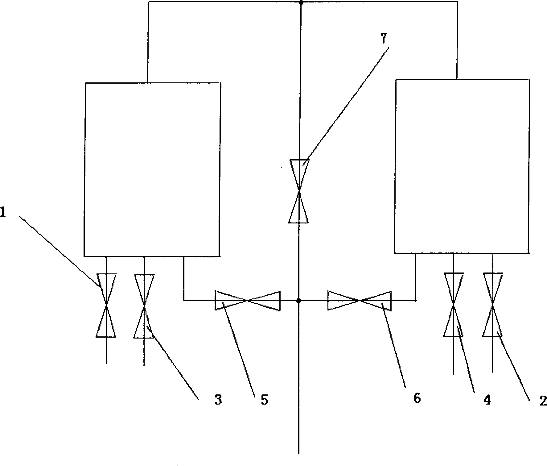
[0062] The first embodiment of the present invention, such as figure 1 As shown in the coupled fixed bed oxygen-enriched continuous gasification process, the solid raw material is coal, and the process is to mix oxygen and air to form oxygen-enriched air, then blow in oxygen-enriched air and steam to produce semi-water gas; the gas-making furnace includes a 1, B, two ordinary gas furnaces, the bottom of A furnace is connected with oxygen-enriched air valve A1, steam valve A3, gas valve A5, and the bottom of B furnace is connected with oxygen-enriched air valve B2, steam valve B4, and gas valve B 6; the gas outlets on the top of furnace A and furnace B are connected in parallel with gas valve C 7, and the other end of gas valve C 7 is connected with the other end of gas valve A 5 and gas valve B 6 through a four-way joint. The other end is connected to the output pipe.

[0063] The cycle time of the gas generation process is 120 seconds, the oxygen concentration in the oxygen-...


PUM


Abstract

The invention discloses oxygen-rich continuous gasification technology for a coupled fixed bed, wherein a solid raw material comprises coal or coke, and a gas raw material comprises oxygen, air and steam; and the oxygen can be mixed with the air into oxygen-rich air first and then is sent into a gas-making furnace, and can also be sent into the gas-making furnace in the form of single gas. The technology is characterized in that the gas-making furnace is that two common gas furnace bodies (A and B) are connected into a whole by a pipeline and a valve, two furnaces alternately upward blow to make gas, and the gas raw material can also comprise carbon dioxide; and the gas-making process comprises the step of the blowing-off of the A and B furnaces, the step of upward blowing of the A furnace, the step of secondary blowing-off of the A and B furnaces, and the step of upward blowing of the B furnace, and the steps are circulated. The gas-making furnace is that the two common gas furnace bodies are connected into a whole by the pipeline and the valve, and the two furnaces alternately upward blow to make gas, so the technology can optimize the distribution of temperature fields in the gas furnaces, reduce the sensible heat loss of semiwater gas, the erosion to pipelines in subsequent working procedures, and the quantity of carry-overs, improve the condition of gas quality, and reduce gas consumption and coal consumption.

Description

technical field [0001] The invention relates to the technical field of coal gasification technology, in particular to the technical field of fixed-bed oxygen-enriched continuous gasification technology. Background technique [0002] Coal gasification is an important step in the production of synthetic ammonia and fuel gas (semi-water gas and water gas), and is the core technology for the development of coal chemical industry. The industrial production of semi-water gas is mainly through the following reactions: first, the oxygen in the air reacts with carbon to generate carbon monoxide and carbon dioxide, which releases heat; secondly, the steam entering the furnace reacts with hot carbon to generate carbon monoxide, carbon dioxide and hydrogen, which absorbs heat. The product of the above reaction together with the nitrogen in the air that has not participated in the reaction constitutes the main component of the semi-water gas. [0003] At present, the fixed-bed coal gasi...

Claims


Application Information

Patent Timeline
Patent Type & Authority Patents(China)
IPC IPC(8): C10J3/14
CPCY02E20/18
Inventor 杨树勋熊兆荣陈东生
Owner 北京名都厚德科技有限公司
Why Eureka
Try Eureka