An optical signal acquisition method used for visual endoscope devices and a visual endoscope device

A technology of optical signal and reflective device, applied in the field of medical devices, can solve the problems of long operation time, increased cost, pain caused by patients, etc., and achieve the effect of expanding the irradiation range and intensity, reducing the frequency of movement, and shortening the operation time.

Active Publication Date: 2009-09-16
DONGGUAN MICROVIEW MEDICAL TECH
View PDF1 Cites 6 Cited by
  • Summary
  • Abstract
  • Description
  • Claims
  • Application Information

AI Technical Summary

Problems solved by technology

During the operation, when the negative pressure in the uterine cavity rises and the pressure difference between the uterine cavity and the negative pressure bottle decreases, so that the embryonic tissue cannot be sucked out, the negative pressure in the uterine cavity is reduced by adjusting the air intake switch, and the embryonic tissue is sucked out. However, in the abortion operation, it is strictly forbidden to inject water or gas into the uterine cavity to expand the uterus. This operation is very likely to cause surgical accidents of blood vessel embolism, which may endanger the life of the patient in serious cases, and there are also problems such as invisible working parts, long operation time, Incomplete operation, etc., and because the equipment is used many times, it is easy to cause cross infection of patients
[0003] The company has applied for an invention patent "A Disposable Visible Human Flow Suction Tube". Although it can be operated visually, when the visible tube is in human organs and its visible head is in close contact with the tissue, it cannot be directly through the lens. To clearly observe the external area, the visual head must be moved away from the human tissue for a certain distance to observe, which causes great pain to the patient and also makes it difficult for the doctor to operate.
[0004] The company applied for a new type of patent "an improved visual endoscopic device", which basically solves the problem of macro-visualization, but it still has the defects of narrow field of view and narrow observation range. In order to observe different angle ranges In the tissue state, the visual head must be constantly moved to find the lesion area, or the inner feeding tube with different visual directions must be replaced, which will increase the cost, time-consuming, and easily cause pain to the patient

Method used


Image

  • An optical signal acquisition method used for visual endoscope devices and a visual endoscope device
  • An optical signal acquisition method used for visual endoscope devices and a visual endoscope device
  • An optical signal acquisition method used for visual endoscope devices and a visual endoscope device

Examples


Embodiment 1

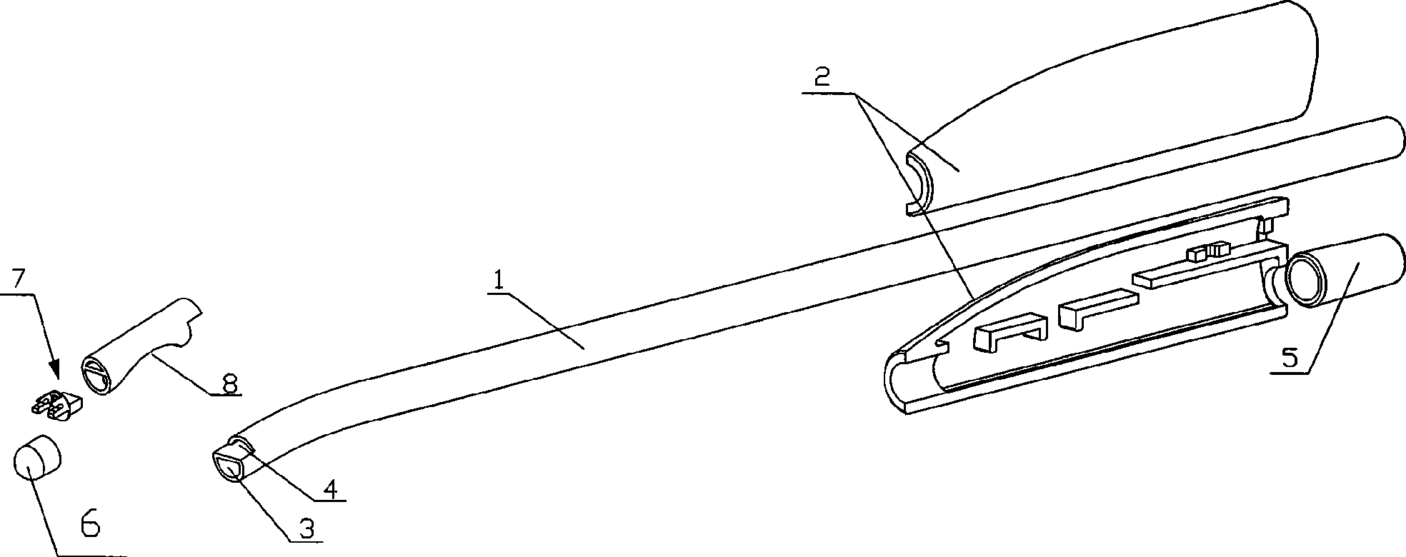
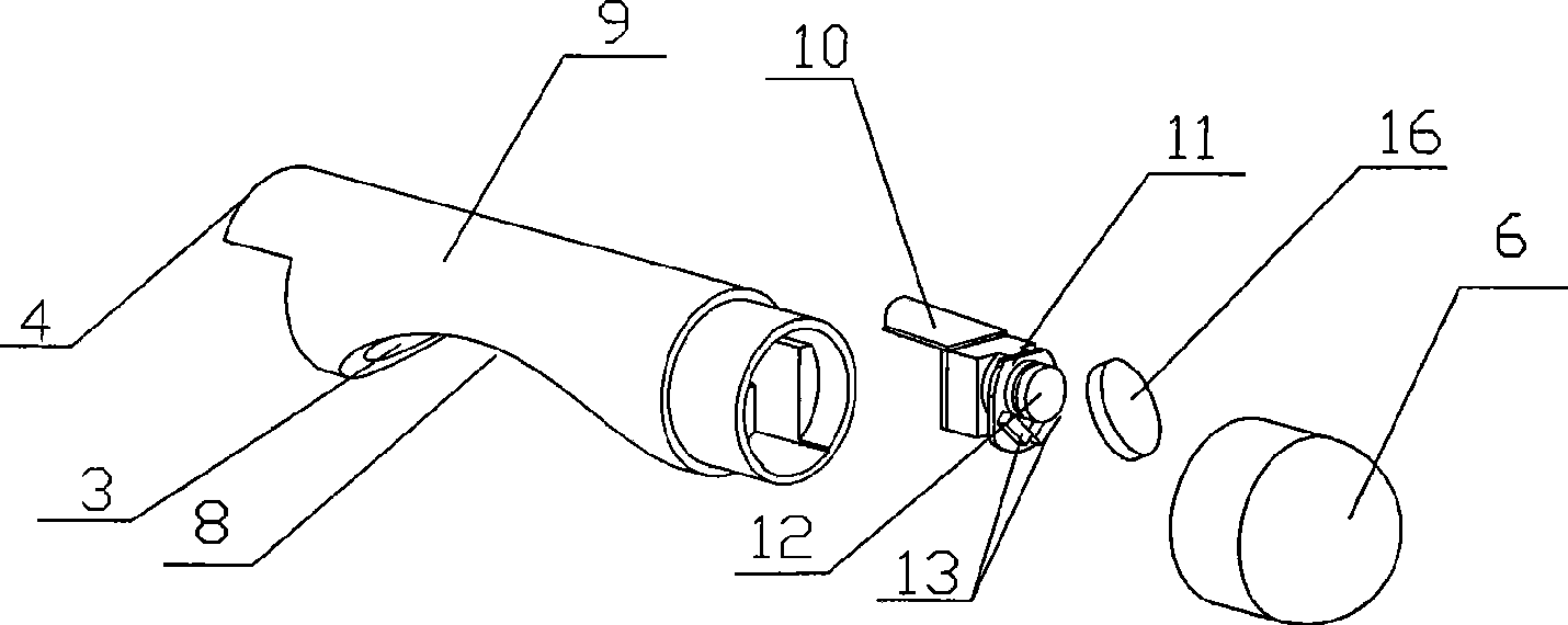
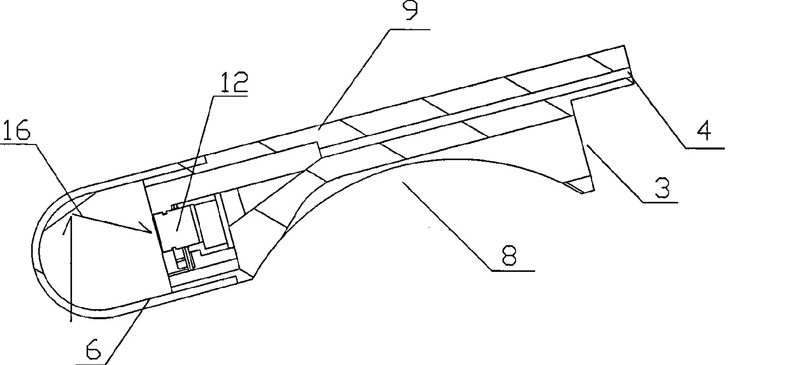
[0038] Embodiment 1: A method for collecting optical signals of a visual endoscopic device provided in this embodiment, which includes a head assembly 7 with a tubular transparent cover 6 at the front end, the head assembly 7 includes a light source and To collect the CMOS module of optical signal, this module comprises a lens 12, and it comprises the following steps:

[0039] 1) In the tubular transparent cover, a reflective device 16 for reflecting the light signal of the observed area is arranged;

[0040] 2) In the reflective area of ​​the reflective device 16, the CMOS module is set, and the displacement space of the lens of the CMOS module is reserved;

[0041] 3) energize and drive the light source, after the light source is irradiated on the area to be observed, the light signal is reflected onto the light reflecting device 16, and the light reflecting device 16 reflects the light signal into the collection area of ​​the CMOS module lens ;

[0042] 4) After the CMOS ...

Embodiment 2

[0047] Embodiment 2: This embodiment provides a method for collecting optical signals of a visual endoscopic device, the steps of which are basically the same as in Embodiment 1, the difference is that it also includes an autofocus device and an image processing device, The autofocus device includes a motor 15 and a control circuit, the image processing device includes an image processing module, the image processing module includes a mirror image correction module, a distortion correction module and a scaling module, and the CMOS module includes a CMOS module 11. Reflector 16 is a convex mirror, and after step 4) of embodiment 1, it also includes the following steps:

[0048] 5) connecting the CMOS module to the autofocus device, wherein the driving device is connected to the CMOS module;

[0049] 6) The CMOS module transmits the image signal formed by it to the control circuit, and the control circuit calculates and controls the driving device to drive the lens of the CMOS m...

Embodiment 3

[0054] Embodiment 3: This embodiment provides a method for collecting optical signals of a visual endoscopy device, the steps of which are basically the same as in Embodiment 2, except that it also includes the following steps:

[0055] 9) Dispersingly arrange several LED lamp groups 13 in the head assembly 7 .

[0056] refer to figure 1 , Image 6 with Figure 7 The present embodiment provides a visual endoscopic device using the above optical signal acquisition method, its structure is basically the same as that of Embodiment 1, the difference is that the direction of the lens 12 is 45° to the axial direction of the fixing member 9 ~90 degrees, the front part of the lens 12 is a see-through member, and the outer area of ​​the see-through member can be seen through the lens. In this embodiment, the lens 12 is perpendicular to the fixing part 9, and the fixing part 9 and the transparent cover 6 are in An opening (not shown) is provided at the connecting portion of the front...


PUM


Abstract

The invention provides an optical signal acquisition method used for visual endoscope devices; in the method, a reflecting device is arranged in the front end area of lens, which is used for reflecting the optical signals in the observed area and the reflected light of the reflector surface is applied so the operation is simple and the collected image is sharp; the invention also provides a visual endoscope device which comprises a top module and an installed reflecting device and a pair of automatically focusing mechanisms and image processing device. Through the installation of the reflecting device in a hemispherical nose module, the range and the strength of exposure of the light source and the field of view of the lens are enlarged and the travel frequency of the top module is reduced; the automatically focusing mechanism can be used for automatically adjusting the relative position of the lens to the reflecting device so as to obtain the sharp images; the image processing devicecan be used for processing image signals collected by CMOS module and reflected by the reflecting device so that the image can truly reflect the size and shape of real objects; the device has a reasonable structure, which can be used for pedestrian flow, the detection of intestines and stomach etc.

Description

technical field [0001] The present invention relates to the field of medical instruments, in particular to a method for collecting optical signals of a visual endoscopic device and a visual endoscopic device thereof. The visual endoscopic device prepared by the method has a wide field of view and can realize automatic focus. Background technique [0002] At present, the general-purpose artificial flow tube is a simple metal hollow tube with a suction port on the top side and a rubber tube and a negative pressure bottle at the end. This kind of artificial flow tube is mostly operated blindly, and the embryo cannot be seen. Operation under the situation of depending on, causes certain misery and harm to the patient. Chinese patent No. 95228318.2 discloses a "double-chamber negative pressure controllable flow suction tube" for blind suction operation. Its basic structure is a double-tube structure. The pressure control channel is connected with an external control switch for ...

Claims


Application Information

Patent Timeline
Patent Type & Authority Applications(China)
IPC IPC(8): A61B1/04G02B23/24
Inventor 沈振权孙绪良
Owner DONGGUAN MICROVIEW MEDICAL TECH
Why Eureka
Try Eureka