Constant current driver of digital semiconductor laser

A technology for constant current drivers and lasers, which is applied in the direction of semiconductor lasers, lasers, laser components, etc., can solve the problems of poor performance of lasers, endangering the safe use of devices, and not seeing specific structures, etc., to improve output stability and protect safe effect

Inactive Publication Date: 2009-09-23
JILIN UNIV
View PDF0 Cites 24 Cited by
  • Summary
  • Abstract
  • Description
  • Claims
  • Application Information

AI Technical Summary

Problems solved by technology

[0005] Second, the output current provided by the driver should be stable enough, because small current changes will lead to great changes in optical power output and changes in device parameters (such as lasing wavelength, noise performance, mode jitter), these changes will directly endanger the device safe use of
[0006] Third, the driver must have sufficient protection measures to ensure the normal and safe operation of the laser, because some electri...

Method used


Image

  • Constant current driver of digital semiconductor laser
  • Constant current driver of digital semiconductor laser
  • Constant current driver of digital semiconductor laser

Examples


Embodiment 1

[0059] Example 1 combined figure 1 Explain the general structure of the present invention

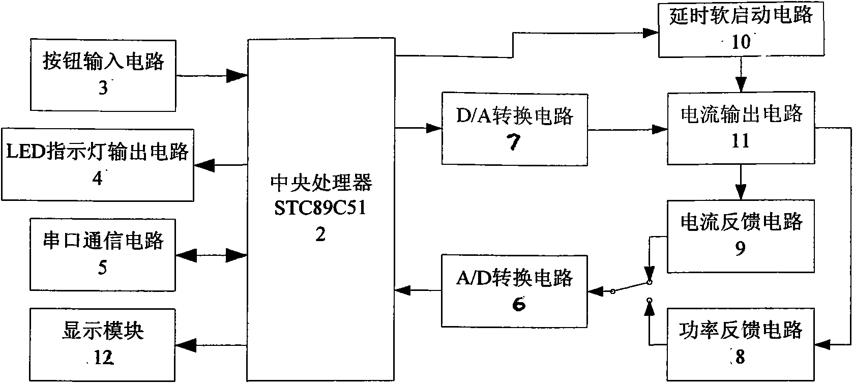
[0060] Such as figure 1 As shown, the digital semiconductor laser constant current driver of the present invention consists of a front panel 1, a central processing unit 2, a button input circuit 3, an LED indicator light output circuit 4, a serial port communication circuit 5, an A / D conversion circuit 6, and a D / A The conversion circuit 7 , the power feedback circuit 8 , the current feedback circuit 9 , the delayed soft start circuit 10 , the current output circuit 11 and the display module 12 are composed.

[0061] The central processing unit 2 is composed of a STC89C51 single-chip microcomputer, and the STC89C51 provides the voltage value corresponding to the set current to the D / A conversion circuit 7 to convert it into an analog voltage, and then controls the current output circuit 11 to generate an output current. In order to ensure the stability of the output current, accordin...

Embodiment 2

[0062] Embodiment 2 CPU 2

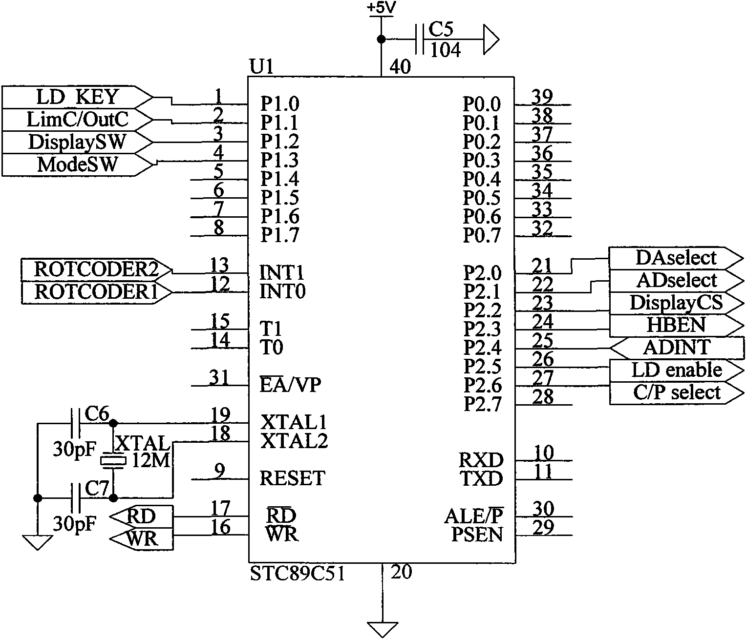
[0063] Such as figure 2 As shown, the central processing unit 2 is composed of STC89C51 single-chip microcomputer; the button input circuit 3 is connected with the INT0, INT1, P1.0, P1.1, P1.2 and P1.3 pins of the STC89C51 to provide the current button information for the central processing unit 2 Input state; LED indicator light output circuit 4 is connected with P1.4, P1.5, P1.6 and P1.7 pins of STC89C51, and the display state of LED indicator light output circuit 4 is controlled by central processing unit 2; display module 12 It is connected with P0.0, P0.1, P0.2, P0.3, P0.4, P0.5, P0.6 and P0.7 pins of STC89C51, and the display of the display module 12 is controlled by the central processing unit 2; The serial port communication circuit 5 is connected with the TXD and RXD pins of STC89C51, and communicates with the upper computer through the serial port communication circuit 5 . A / D conversion circuit 6 is connected with P0 port, P2.1, P2.3, ...

Embodiment 3

[0064] Embodiment 3 button input circuit 3

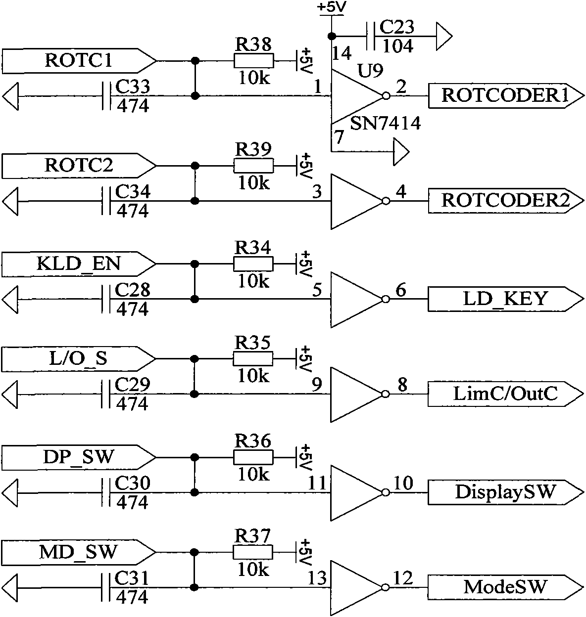
[0065] Such as image 3As shown, the button input circuit 3 includes: the 14th pin of the Schmitt trigger chip SN7414 is connected to the +5V power supply, and is grounded through the filter capacitor C32 (0.1uF); the 7th pin of the SN7414 is grounded; the 1st pin of the SN7414 is connected to the resistor R38 (10kΩ) is connected to +5V power supply, grounded through capacitor C33 (0.47uF), connected to port "ROTC1", which is pin 1 of the rotary encoder corresponding to the current adjustment knob on the front panel 1; pin 2 of SN7414 is connected to port "ROTCODER1 "That is, the external interrupt pin INT0 of the central processing unit STC89C51; the 3 pin of the SN7414 is connected to the +5V power supply through the resistor R39 (10kΩ), grounded through the capacitor C34 (0.47uF), and connected to the port "ROTC2", which is the current adjustment of the front panel 1 The 2 pins of the rotary encoder corresponding to the knob; th...


PUM


Abstract

The invention relates to a constant current driver of a digital semiconductor laser, belonging to the technical field of electronic equipment. The structure of the constant current driver comprises a front panel (1), a central processing unit (CPU) STC89C51 (2), a button input circuit (3), an LED indicating lamp output circuit (4), a serial communication circuit (5), an A/D converting circuit (6), a D/A converting circuit (7), a power feedback circuit (8), a current feedback circuit (9), a time delay soft start circuit (10), a current output circuit (11) and a display module (12). The constant current driver has the output current of 0-2A, adopts negative feedback structure, effectively improves the output stability, and has the short-term stability being lower than 38ppm; two driving ways which are constant current and constant power are provided by the constant current driver, so that the constant current driver is convenient for use on different occasions; the constant current driver has the protecting functions such as current limitation, soft start, time delay and the like, so as to effectively guarantee the safety of the laser; and program can be controlled and upgraded in system.

Description

technical field [0001] The invention belongs to the technical field of electronic equipment, and in particular relates to a driving power supply for a semiconductor laser. Background technique [0002] With the rapid development of science and technology, semiconductor laser technology has been more and more widely used in various fields such as national economy and national defense construction. Compared with other lasers, semiconductor lasers have some incomparable characteristics. For example, semiconductor lasers can be excited by 2-3 volts, while common helium-neon lasers need to be excited by high voltage 1500 volts. The excitation method of the laser is much safer, and its efficiency is tens of times higher than that of ordinary lasers. In some measuring instruments, semiconductor lasers are used for illumination, which can meet the requirements of good monochromaticity, good coherence, and high beam alignment accuracy. In addition, semiconductor lasers are widely u...

Claims


Application Information

Patent Timeline
IPC IPC(8): H01S5/042G05B19/042
Inventor 汝玉星单江东吴戈田小建
Owner JILIN UNIV
Why Eureka
Try Eureka