
Identical reaction kettle reel-to-reel plasma ultrasonic supercritical non-aqueous dyeing

An anhydrous dyeing and reaction kettle technology, applied in dyeing method, vibration treatment, treatment of textile material containers, etc., can solve problems such as inability to solve the problem of textile surface pretreatment, inability to meet the requirements of safety, and the system works continuously at a uniform speed. Achieve the effect of shortening dyeing time, improving production efficiency and simple process

Inactive Publication Date: 2009-10-14
冷博
View PDF1 Cites 24 Cited by
  • Summary
  • Abstract
  • Description
  • Claims
  • Application Information

AI Technical Summary

Problems solved by technology

[0003] The existing supercritical carbon dioxide anhydrous dyeing technology cannot solve the problem of surface pretreatment of textiles, resulting in generally low dyeing fastness
The chemical pretreatment outside the machine makes it inevitable that toxic chemicals will remain on the surface of textiles, which cannot meet the increasingly stringent requirements for all-natural and human clothing safety.
[0004] Another reason why the existing supercritical carbon dioxide anhydrous dyeing technology only stays in the laboratory stage and cannot be commercialized on a large scale is that the existing devices basically work intermittently and cannot work continuously at a uniform speed
In the patent application with application number 200710027112.6 titled "Production System and Production Process for Continuous Dyeing Using Supercritical Fluid", the inventor tried to ensure continuous production by alternately dyeing with multiple sets of dyeing devices, but in practice The series connection or parallel connection of multiple groups of intermittently working dyeing devices just forms more intermittent, but cannot necessarily make the system work continuously at a uniform speed

Method used


Image

  • Identical reaction kettle reel-to-reel plasma ultrasonic supercritical non-aqueous dyeing

Examples


Embodiment 1

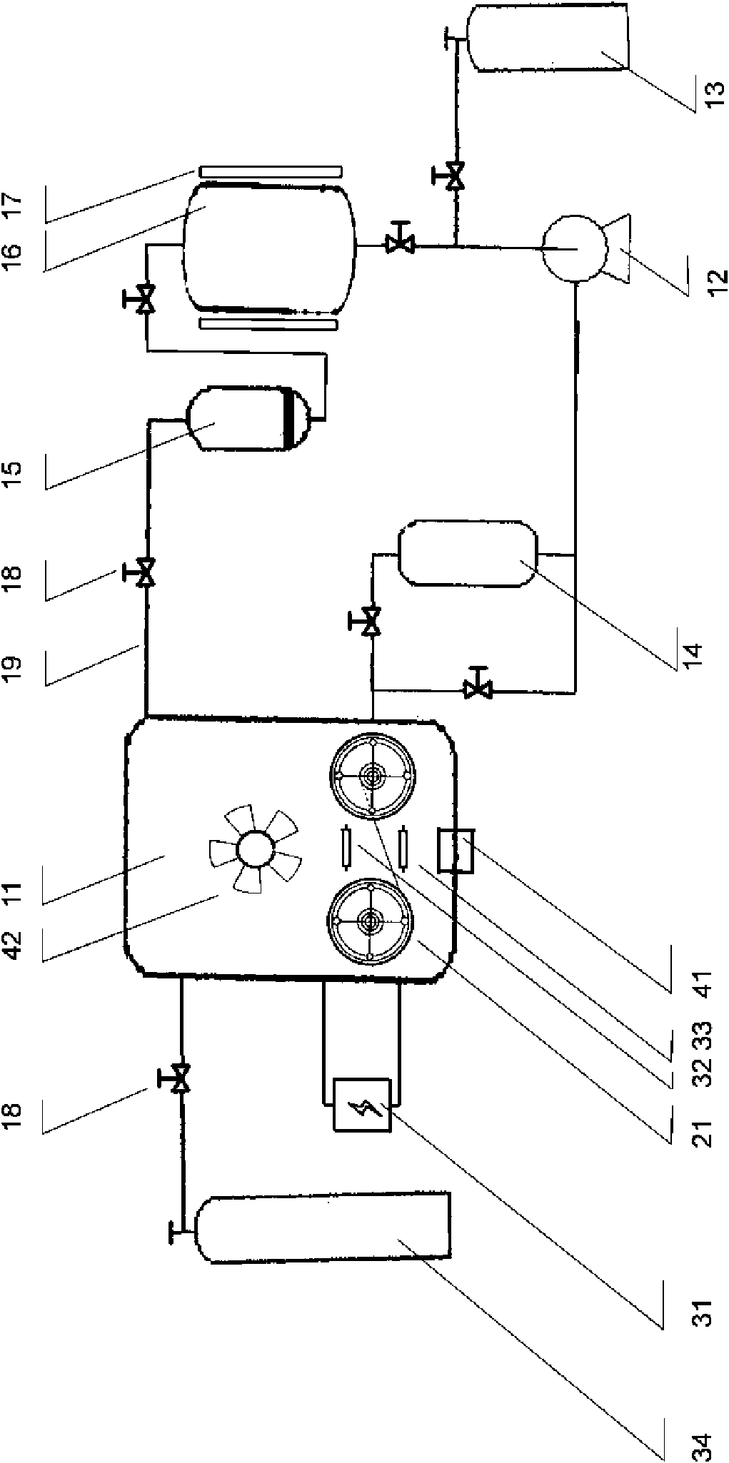
[0019]Embodiment 1, the same reactor roll-to-roll plasma ultrasonic supercritical textile anhydrous dyeing, the greige cloth is packed into the roll-to-roll or shaft-to-shaft winding device (21) in the reactor, with a vacuum pump (preferably a Luo with a large air extraction capacity) Vacuum pump) vacuumizes the airtight reaction kettle (11) made of high-pressure resistant transparent glass (to about 10Pa), feeds oxygen into the reaction kettle (11) from the gas cylinder (34), and gives the reaction kettle (11) The upper electrode (32) and the lower electrode (33) of the inner plasma generator (31) are energized, the plasma parameters are measured by a Langmuir (Langmuir) probe, and the reel-to-reel or reel-to-reel winding device (21) is turned on to enable The textile starts to be wound at a constant speed, and the surface of the textile is modified by capacitively coupled low-pressure glow discharge. The plasma reaction is stopped after the power is turned off, and a small am...


PUM


Abstract

The invention discloses an identical reaction kettle reel-to-reel plasma ultrasonic supercritical non-aqueous dyeing system, comprising a general control console, a carbon dioxide storage bottle, a high-pressure pump, a dye tank, a heat exchange device, a reaction kettle, a dye recycling tank, a filter, a condenser, a liquid carbon dioxide storage tank, a flow meter, a valve and a pipeline, and characterized in that the reaction kettle is provided with an upper electrode and a lower electrode of a plasma generator, an exhaust valve and a vacuum pump, is internally provided with one or a plurality of groups of reel-to-reel or axis-to-axis wind and relative motors, is also internally provided with one or a plurality of groups of agitating devices and relative motors, and is embedded with an ultrasonic transducer connected with an ultrasonic wave generation device. The plasma realizes the modification for the surface of material, the ultrasonic wave disperses the dyes uniformly, the supercritical carbon dioxide realizes non-aqueous dyeing, and the reel-to-reel way realizes non-intermittent continuous industry production. The invention can meet the most rigorous environment-friendly demand and product safety demand.

Description

technical field [0001] The invention relates to a roll-to-roll plasma ultrasonic supercritical anhydrous dyeing method and system in the same reactor, and belongs to the dyeing field of textiles such as yarn, cloth (including non-woven fabrics), and garments. Of course, the invention can also be applied to metal sheets Surface modification and dyeing of plastic film, paper and other rollable materials. Background technique [0002] The traditional dyeing process of textiles such as fibers, cloth (including non-woven fabrics), and garments consumes a lot of water resources and discharges a lot of sewage. The water consumption is about 3.7-4.5 tons / 100 meters (according to the width of 180 cm), and the use of various additives makes the sewage reuse rate less than 10%. An enterprise with an annual output of 100 million meters of printing and dyeing cloth consumes as much water as all the residents of a medium-sized city. In 2005, China's printing and dyeing output was 36.2 b...

Claims


Application Information

Patent Timeline
Patent Type & Authority Applications(China)
IPC IPC(8): D06P1/94D06P5/20D06M10/00
CPCD06B13/00D06B19/00D06B23/14
Inventor 冷博
Owner 冷博
Learn More