Strong correlation electron system-based organic solar cell and preparation method thereof

A solar cell and strong correlation technology, which is applied in the direction of electrical solid-state devices, semiconductor/solid-state device manufacturing, circuits, etc., can solve problems such as the inability to explain the main physical properties of the system, and achieve the goal of improving electron transmission capabilities, blocking damage, and improving transmission capabilities Effect

Inactive Publication Date: 2009-10-21
PEKING UNIV
View PDF0 Cites 39 Cited by
  • Summary
  • Abstract
  • Description
  • Claims
  • Application Information

AI Technical Summary

Problems solved by technology

At this time, the single-electron approximation is still used, and the interaction is simpl

Method used


Image

  • Strong correlation electron system-based organic solar cell and preparation method thereof
  • Strong correlation electron system-based organic solar cell and preparation method thereof
  • Strong correlation electron system-based organic solar cell and preparation method thereof

Examples


Embodiment 1

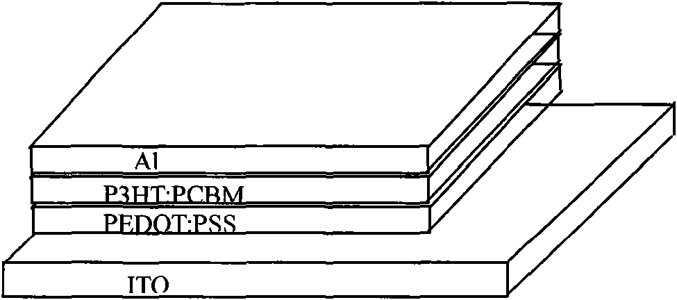
[0028] Embodiment 1, reference device one

[0029] Prepare reference device 1 according to the following steps:

[0030] (1) Cleaning ITO (indium tin oxide): Ultrasonic cleaning in deionized water, acetone, and ethanol for 10 minutes, and then processing in a plasma cleaning instrument for 1 minute;

[0031] (2) Spin-coat the hole buffer layer PEDOT:PSS on the anode ITO, wherein PEDOT:PSS / H in the PEDOT:PSS aqueous solution 2 O=1 / 4 (volume ratio, the same below), filter head pore size 0.2 microns, rotating speed 3000 rpm, spin coating time 30 seconds, anneal at 200°C after spin coating, after 5 minutes in air, in vacuum (<10Pa ) for 15 minutes, cool down;

[0032] (3) Spin-coat the photoactive layer P3HT:PCBM mixed solution on the hole buffer layer PEDOT:PSS, wherein the concentration of the mixed solution is P3HT:PCBM / ortho-dichlorobenzene=(15mg:12mg) / ml, that is, every milliliter of ortho-dichlorobenzene Contain 15mgP3HT and 12mg PCBM in the chlorobenzene solvent, the ape...

Embodiment 2

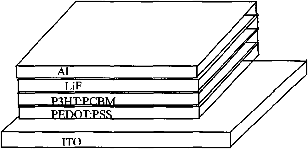
[0035] Embodiment 2, reference device two

[0036] Reference device 2 was prepared according to the following steps:

[0037] (1) Cleaning ITO (indium tin oxide): Ultrasonic cleaning in deionized water, acetone, and ethanol for 10 minutes, and then processing in a plasma cleaning instrument for 1 minute;

[0038] (2) Spin-coat the hole buffer layer PEDOT:PSS on the anode ITO, wherein PEDOT:PSS / H in the PEDOT:PSS aqueous solution 2 O=1 / 4, filter head pore size 0.2 micron, rotating speed 3000 rpm, spin coating time 30 seconds, anneal at 200°C after spin coating, after 5 minutes in air, 15 minutes in vacuum (<10Pa), cool down;

[0039] (3) Spin-coat the photoactive layer P3HT:PCBM mixed solution on the hole buffer layer PEDOT:PSS, wherein the mixed solution concentration is P3HT:PCBM / o-dichlorobenzene=(15mg:12mg) / ml, and the filter head aperture is 0.2 microns , rotating speed 600~800 rev / min, spin coating time 15 seconds, anneal at 150 ℃ after the solvent volatilizes after spi...

Embodiment 3

[0043] Embodiment 3, implementation device

[0044] 1. Materials:

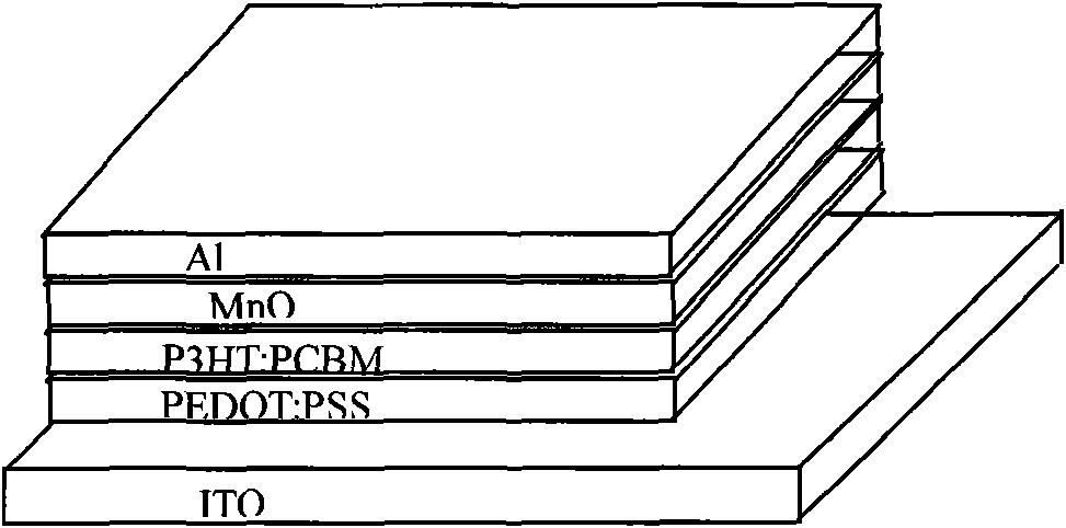
[0045] The OSC device based on classical materials adds an electron buffer layer formed by a strongly correlated electron system compound. The structure of the OSC is: ITO / PEDOT:PSS / P3HT:PCBM / MnO / Al. First, the hole buffer layer PEDOT:PSS is spin-coated on the ITO, and then the photoactive layer P3HT:PCBM is spin-coated on the hole buffer layer, and then the strongly correlated electron system compound-manganese oxide (MnO) is vacuum evaporated on the P3HT:PCMB. ), and finally vacuum-evaporated cathode Al on MnO. Device structure see Figure 1c .

[0046] 2. Device preparation method:

[0047] (1) Cleaning ITO (indium tin oxide): Ultrasonic cleaning in deionized water, acetone, and ethanol for 10 minutes, and then processing in a plasma cleaning instrument for 1 minute;

[0048] (2) Spin-coat the hole buffer layer PEDOT:PSS on the anode ITO, where PEDOT:PSS aqueous solution PEDOT:PSS / H 2 O=1 / 4, filter he...


PUM

PropertyMeasurementUnit
Thicknessaaaaaaaaaa
Thicknessaaaaaaaaaa

Abstract

The invention discloses a strong correlation electron system-based organic solar cell and a preparation method thereof. The organic solar energy cell comprises a positive pole, a hole buffer layer, a photoactive layer and a negative pole, and is characterized in that: the organic solar energy cell also comprises an electron buffer layer which is arranged between the photoactive layer and the negative pole and is made of a material which is strong correlation electron system compound; and by using the property that the strong correlation electron system compound performs insulating state to metal state conversion when injected with charges, the organic solar energy cell improves the electron transmission capacity at the position of the interface between an organic layer and an inorganic electrode, thereby improving the short circuit current Isc and power conversion efficiency PCE of a device, preventing the damages caused by a deposited metal cathode to the organic layer, reducing the drawbacks of the device, suppressing the degradation of the device; and compared with the common LiF electronic buffer layer, the electronic buffer layer of the invention has the advantages of simple and convenient manufacturing process, easy control and excellent device performance.

Description

technical field [0001] The invention belongs to the field of organic solar cells (OSC), and in particular relates to an organic solar cell based on a strongly correlated electron system and a preparation method thereof. Background technique [0002] A solar cell is a device that directly converts light energy into electrical energy through the photoelectric effect or photochemical effect, also known as a photovoltaic device. Organic solar cells are solar cells whose core is composed of organic materials. They have the advantages of simple manufacture, low temperature in the preparation process, low cost, and large-area flexible devices. Tang of Kodak Research Laboratory reported the first PV (photovoltaic) heterojunction device (C.W.Tang, "Two-layer organic photovoltaic cell", Appl. Phys. Lett. 1986, 48, 183). The basic structure of an organic solar cell includes an anode, a hole transport layer, a photoactive layer, an electron transport layer, and a cathode. The conversi...

Claims


Application Information

Patent Timeline
IPC IPC(8): H01L51/42H01L51/44H01L51/46H01L51/48
CPCY02E10/50Y02E10/549
Inventor 肖立新罗佳秀陈志坚龚旗煌
Owner PEKING UNIV
Why Eureka
Try Eureka