Bimetal wear resistant composite tube

A composite pipe and bimetal technology, applied in the pipeline field, can solve the problems of inability to solve the wear resistance and weldability, the wear resistance and toughness are not optimal, and the anti-abrasive wear performance is poor, so as to solve the problems of weldability and weldability. The contradiction of wear resistance, the effect of good internal quality and high temperature resistance

Inactive Publication Date: 2009-12-02
郑州神牛铸造有限公司
View PDF1 Cites 15 Cited by
  • Summary
  • Abstract
  • Description
  • Claims
  • Application Information

AI Technical Summary

Problems solved by technology

[0009] The hardness is much lower and the abrasive wear resistance is poor
Because it is a single material, it cannot solve the contradiction between wear resistance and weldability, and the wear resistance and toughness are not optimal
Sand casting is generally used, which is prone to defects such as sand washing, slag inclusions, and pores, and the dimensional accuracy is poor
[0010] Chines

Method used


Image

  • Bimetal wear resistant composite tube
  • Bimetal wear resistant composite tube
  • Bimetal wear resistant composite tube

Examples


Embodiment 1

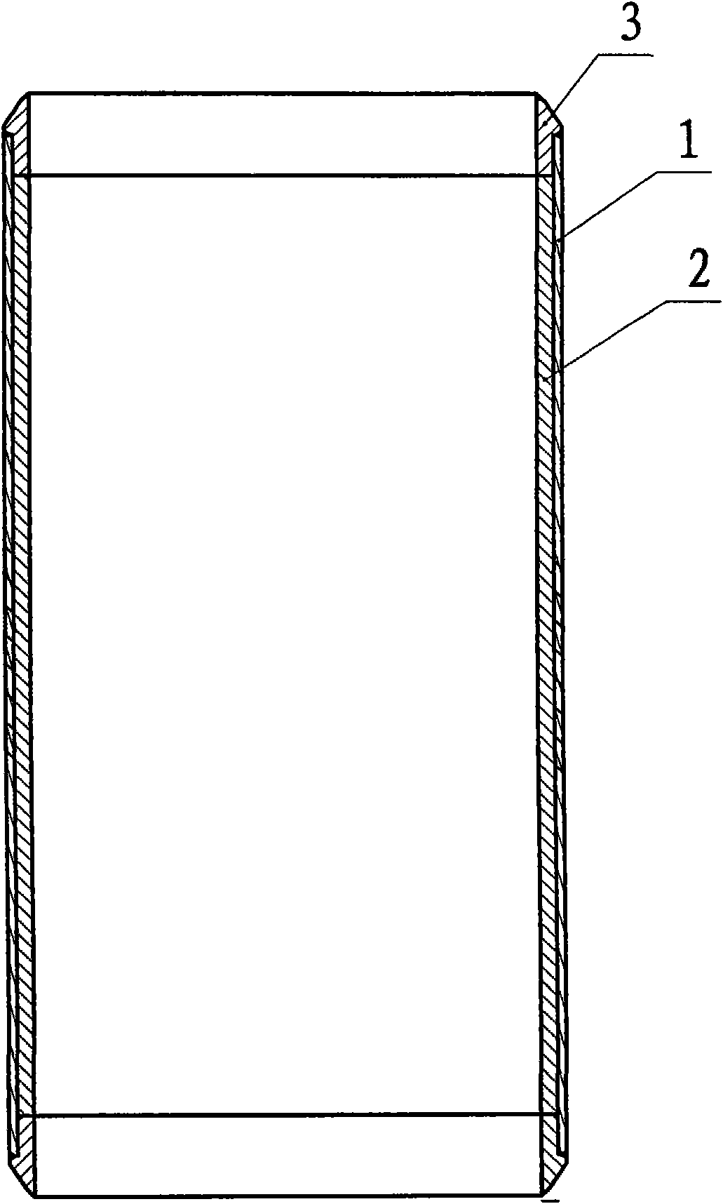
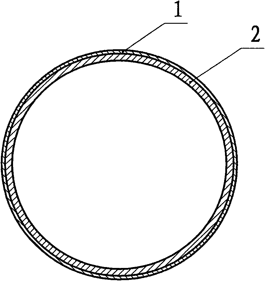
[0060] Embodiment one: see figure 1 , figure 2 , a bimetal wear-resistant composite pipe in the figure, the pipe contains an outer carbon steel layer 1 and an inner wear-resistant high-chromium cast iron layer 2, the carbon steel layer 1 is made of three materials: ZG15, ZG25, and ZG35 Any one of the three materials, the material of the wear-resistant layer 2 is any one of the three materials KMTBCr26G, KMTBCr20MoG, KMTBCr15MoG, and the composition of the three materials is shown in Table 1 below. The composite pipe is a straight pipe; it is made by centrifugal casting process; it includes the following steps:

[0061] (1) Pipe mold preheating; select a suitable pipe mold and preheat to 500°C;

[0062] (2) Spray paint; spray 2.0-2.5MM paint after cooling the pipe mold to 250-300°C;

[0063] (3) Pouring the outer wall of low-carbon steel; during the pouring process, the rotational speed of the centrifugal pipe mold is set at 140-150 rpm, and the pouring temperature is 1550-...

Embodiment 2

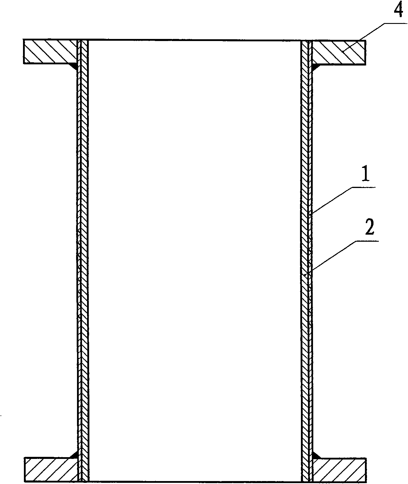
[0067] Embodiment two: see image 3 , figure 2 , the second embodiment is basically the same as the first embodiment, and the same symbols in the figure represent the same meaning, and the similarities will not be repeated. The flange 4, the inner ring of the flange 4 matches the diameter of the end of the composite pipe, and the inner ring of the flange 4 is welded into one body with the carbon steel layer 1 of the composite pipe.

Embodiment 3

[0068] Embodiment three: see Figure 4 , Figure 5 , a bimetal wear-resistant composite pipe in the figure, the pipe contains an outer carbon steel layer 1 and an inner wear-resistant high-chromium cast iron layer 2, the carbon steel layer 1 is made of three materials: ZG15, ZG25, and ZG35 Any one of the three materials, the material of the wear-resistant layer 2 is any one of the three materials KMTBCr26G, KMTBCr20MoG, KMTBCr15MoG, and the composition of the three materials is shown in Table 1 below. The composite pipe is a curved pipe, which is manufactured by the lost foam casting process, including the following steps:

[0069] (1) Precast, press or simmer the outer wall of the elbow;

[0070] (2) EPS foam type attached to the inner wall of the elbow;

[0071] (3) Brush the surface of EPS foam with special coating for lost foam 2-4 times;

[0072] (4) drying in a drying room at 45-50°C;

[0073] (5) Put the model into the sand box and place it on the vibrating table t...


PUM


Abstract

The invention provides a bimetal wear resistance composite tube, which comprises a carbon steel layer in an outer layer and a wear resistant high-chromium cast iron layer in an inner layer; the carbon steel layer is made of one of three materials of ZG15, ZG25 and ZG35; and the wear resistant layer is made of one of three materials of KMTBCr26G, KMTBCr20MoG and KMTBCr15MoG. The composite tube is one of a straight tube, an elbow tube, a tee tube, a four-way tube and a special tube. The composite tube has the advantages of jointly utilizing the characteristics of the carbon steel and the high-chromium cast iron, solving the problems of wear resistance and toughness, having low cost, and also solving the unsolvable contradiction of weldability and wear resistance existing in the composite tube adopting the single material, along with long service life and convenient transportation, assembly and use.

Description

1. Technical field [0001] The invention relates to a pipeline used for long-distance pressure transportation of materials, in particular to a bimetal wear-resistant composite pipe. 2. Background technology [0002] In mining, smelting, coal, electric power and other industries, long-distance pressure transportation is used for material transportation, and pipelines are under considerable pressure and undergo severe wear and tear. The conveying pipeline is generally composed of straight pipes and bent pipes with different angles. When the high-speed air or liquid flow entraining solid powder flows through the pipeline, the solid particles will cause serious wear to the pipeline, especially when flowing through the bent pipe, under the action of centrifugal force The wear rate of the outer wall of the bent pipe is much faster than that of the straight pipe. Pipes made of a single material cannot meet the requirements of this working condition. Considering the safety of its u...

Claims


Application Information

Patent Timeline
IPC IPC(8): F16L9/02F16L57/06F16L43/00F16L41/02F16L41/03F16L41/08
Inventor 姚万林王海洋
Owner 郑州神牛铸造有限公司
Why Eureka
Try Eureka