Minitype F-P reflective index sensor of full optical fiber ring-type reflecting surface structure
A technology of a refractive index sensor and a reflective surface, applied in the field of optical sensing, can solve the problems that the contrast ratio of the Fibonacci cavity is easily affected by the light source, the long-period fiber grating is greatly affected by the bending, and the bare fiber is easily polluted, and achieves high reliability. , small size, simple effect
- Summary
- Abstract
- Description
- Claims
- Application Information
AI Technical Summary
Problems solved by technology
Method used
Image

Examples
Embodiment Construction
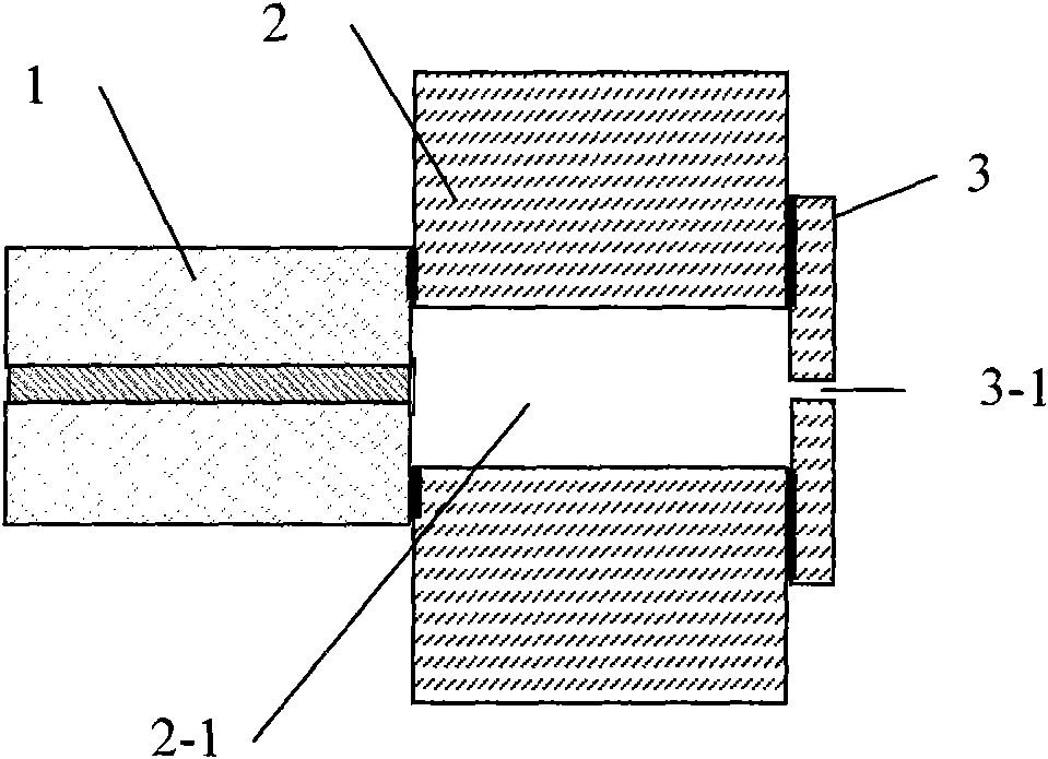
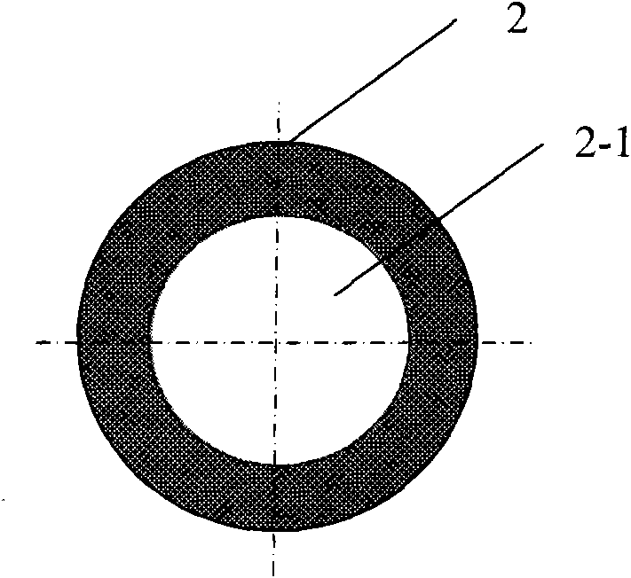
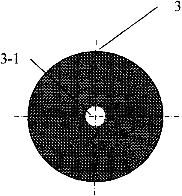
[0020] see figure 1 , shown in the figure is the sensor structure of the present invention, which is composed of ordinary single-mode optical fiber 1, large-diameter hollow-core optical fiber 2 and optical fiber 3 with a through hole in the center, ordinary single-mode optical fiber 1, large-core diameter hollow-core optical fiber 2. The optical fiber 3 with a through hole in the center is welded and fixed in sequence, and the hollow core fiber 2 with a large core diameter communicates with the optical fiber 3 with a through hole in the center;
[0021] The two ports of the core (that is, the F-P cavity) of the large-core hollow-core fiber 2 are respectively closed by the ordinary single-mode fiber 1 and the optical fiber 3 with a through hole in the center, and the inside of the core of the large-core hollow-core fiber 2 (2 in the figure -1 place) can only communicate with the external environment through the fiber core (3-1 place among the figures) of the optical fiber 3 wit...
PUM
| Property | Measurement | Unit |
|---|---|---|
| The inside diameter of | aaaaa | aaaaa |
| Outer diameter | aaaaa | aaaaa |
| The inside diameter of | aaaaa | aaaaa |
Abstract
Description
Claims
Application Information
PatSnap Eureka turns technology decisions into work you can execute. Powered by our Innovation Knowledge Graph, it runs expert workflows across engineering, life sciences, materials and intellectual property. Get your review-ready output in minutes.


