Powder metallurgy bolster and production technology thereof
A powder metallurgy and production process technology, applied in textiles and papermaking, etc., can solve the problems of low strength, low tensile strength, failure, etc., and achieve the effect of saving raw materials, low processing cost, and less waste.
- Summary
- Abstract
- Description
- Claims
- Application Information
AI Technical Summary
Problems solved by technology
Method used
Image

Examples
Embodiment 1
[0029] Step 1. Ingredients
[0030] 1.5% (weight) copper powder, 0.4% (weight) graphite powder, 0.7% (weight) zinc stearate, 0.8% (weight) manganese sulfide, 0.5% (weight) phosphorus iron (P-Fe) powder , and the rest is reduced iron powder for mixing and preparing materials. Iron powder is made by mixing iron powders of different particle sizes. The weight ratio between -100 mesh iron powder, -200 mesh iron powder and -325 mesh iron powder is: 45%, 30% and 25%; the particle size of copper powder -400 mesh; the particle size of graphite powder is -450 mesh.
[0031] Step 2. Compacting
[0032] Use a powder metallurgy press (model HPP-600S) and a mold to press the mixture obtained in step 1 into a compact with a pressure of 160 tons. After the compact is formed, the density of the compact is 6.7g / cm 3 . .
[0033] Step three, sintering
[0034] Place the ingot foot compact in a seven-stage sintering furnace for sintering, and sinter at a high temperature of 1140°C for 3 ho...
Embodiment 2
[0044] Step 1. Ingredients
[0045] 3.0% (weight) copper powder, 0.4% (weight) graphite powder, 0.5% (weight) zinc stearate, 0.3% (weight) manganese sulfide, 1.0% (weight) phosphorus iron powder, and the rest are reduced iron powder for mixing. Iron powder is made by mixing iron powders of different particle sizes. The weight ratio between -100 mesh iron powder, -200 mesh iron powder and -325 mesh iron powder is: 50%, 30% and 20%; the particle size of copper powder -500 mesh; the particle size of graphite powder is -500 mesh.
[0046] Step 2. Compacting
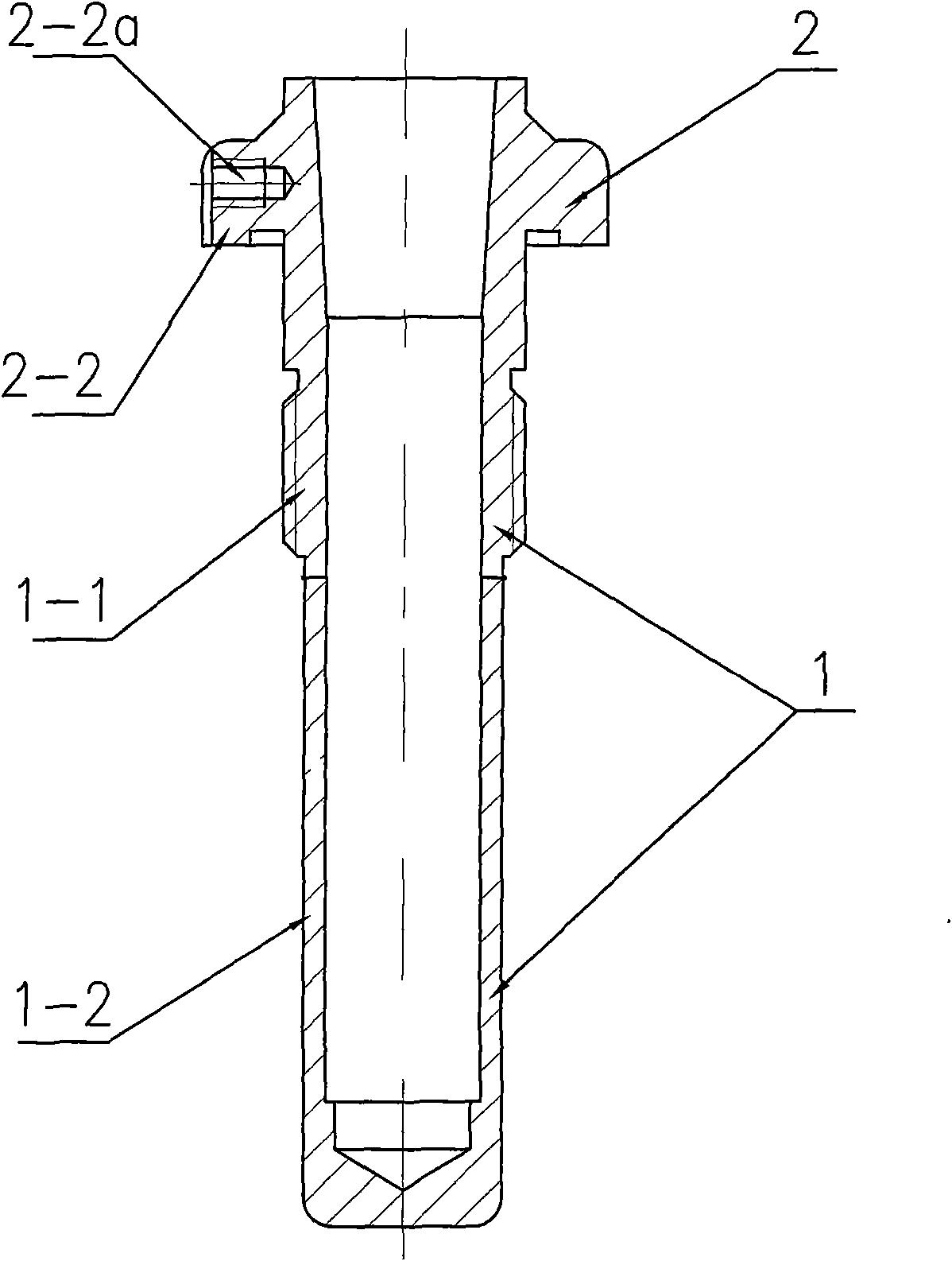
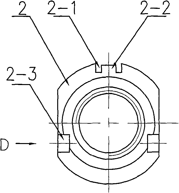
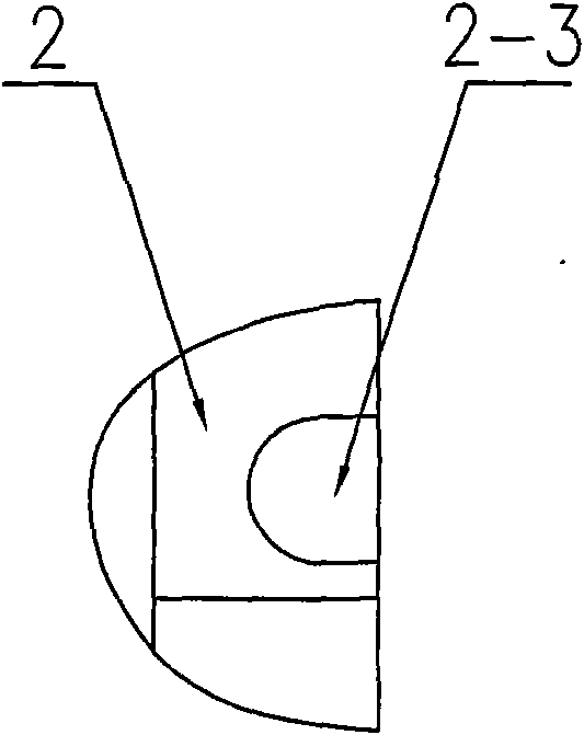
[0047] Use a powder metallurgy press (model HPP-600S) and a mold to divide the oil storage pipe 1 into an upper section 1-1 and a lower section 1-2 to compact respectively, and the flange 2 is arranged on the upper section 1-1, and then the formed The upper section 1-1 compact and the lower section 1-2 compact are welded together to obtain the ingot foot compact. After the compact is formed, the compact density is 7.5g / cm ...
Embodiment 3
[0050] Step 1. Ingredients
[0051] 2.0% (weight) copper powder, 0.4% (weight) graphite powder, 1.0% (weight) zinc stearate, 0.5% (weight) manganese sulfide, 0.5% (weight) phosphorus iron powder, and the rest are reduced iron powder for mixing. Iron powder is made by mixing iron powders of different particle sizes. The weight ratio between -100 mesh iron powder, -200 mesh iron powder and -325 mesh iron powder is: 45%, 30% and 25%; the particle size of copper powder -400 mesh; the particle size of graphite powder is -450 mesh. All the other steps are the same as in Example 1.
PUM
| Property | Measurement | Unit |
|---|---|---|
| Granularity | aaaaa | aaaaa |
| Granularity | aaaaa | aaaaa |
| Density | aaaaa | aaaaa |
Abstract
Description
Claims
Application Information
 - Generate Ideas
- Intellectual Property
- Life Sciences
- Materials
- Tech Scout
- Unparalleled Data Quality
- Higher Quality Content
- 60% Fewer Hallucinations
Browse by: Latest US Patents, China's latest patents, Technical Efficacy Thesaurus, Application Domain, Technology Topic, Popular Technical Reports.
© 2025 PatSnap. All rights reserved.Legal|Privacy policy|Modern Slavery Act Transparency Statement|Sitemap|About US| Contact US: help@patsnap.com