Solar cell of sandwich structure consisting of Si/FeSi2/Si and manufacturing method thereof

A solar cell and sandwich technology, which is applied in the direction of final product manufacturing, sustainable manufacturing/processing, circuits, etc., can solve the problems of low photoelectric conversion efficiency and low open circuit voltage, so as to improve photoelectric conversion efficiency, reduce high defect density, The effect of simple production process

Inactive Publication Date: 2010-06-02
HUBEI UNIV
View PDF0 Cites 4 Cited by
  • Summary
  • Abstract
  • Description
  • Claims
  • Application Information

AI Technical Summary

Problems solved by technology

[0005] The purpose of the present invention is aimed at current FeSi 2 Due to the problems of low open circuit voltage and low photoelectric conversion efficiency in photovoltaic technology, a wide-narrowband mixed Si / FeSi 2 New device structure and manufacturing method of solar cell with / Si sandwich structure

Method used


Image

  • Solar cell of sandwich structure consisting of Si/FeSi2/Si and manufacturing method thereof
  • Solar cell of sandwich structure consisting of Si/FeSi2/Si and manufacturing method thereof
  • Solar cell of sandwich structure consisting of Si/FeSi2/Si and manufacturing method thereof

Examples


Embodiment Construction

[0034] Below in conjunction with accompanying drawing, concrete design and implementation mode of the present invention are described in detail:

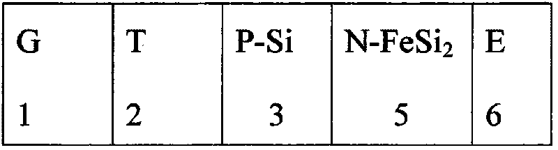
[0035] refer to Figure 5 (a), Si / FeSi designed for the present invention 2 / Si thin film photovoltaic cell device structure diagram. In order to match the manufacturing process of the current amorphous silicon thin-film solar energy production line, this design uses transparent materials as the substrate, such as glass. When the P-i-N structure is adopted, the SnO with a textured structure using the transparent conductive glass TCO as the transparent substrate 1 2 : F on the transparent conductive film 2, first deposit a layer of 400nm thick boron-doped P-type silicon doped layer 3, the doping concentration is 5 × 10 19 / cm 2 . Then deposit a second layer of undoped intrinsic FeSi with a thickness of 2000nm 2 layer, continue to deposit a phosphorus-doped n-type silicon doped layer with a thickness of 2000nm, and a doping conc...


PUM


Abstract

The invention discloses a novel ultra-thin efficient solar cell of a sandwich structure consisting of Si/FeSi2/Si and a manufacturing method thereof. The method mainly substitutes a beta-FeSi2 material for the intrinsic silicon layer of a silicon solar cell of the conventional PIN structure. As a band gap of the beta-FeSi2 material is narrower than that of a Si material, the energy band structure of a heterojunction consisting of the beta-FeSi2 and the Si enables photon-generated carriers generated by illumination to be separated and moved directionally and reversely under the effect of the built-in field of the heterojunction so as to realize a function of photovoltaic conversion. The adopted beta-FeSi2 has a photoabsorption coefficient of 105/cm, which is two orders of magnitude greater than 103/cm of a monocrystalline silicon, and has higher electron and hole mobilities than those of the monocrystalline silicon. In the solar cell of a wide/narrow/wide band gap sandwich structure consisting of the beta-FeSi2 and the Si, an open-circuit voltage, which is determined by P-type and N-type silicon layers at both ends of the beta-FeSi2 layer, can reach over 0.7 V; and the solar cell can have the photovoltaic conversion efficiency equal to that of a crystal silicon solar cell within 5 microns of the total effective thickness. The ultra-thin efficient solar cell of the sandwich structure consisting of the Si/FeSi2/Si has the advantages of ultra thin, high efficiency, long service life and low cost equal to that of an amorphous silicon thin film solar cell, which can be directly applied to the commercialization production of solar cells.

Description

technical field [0001] The invention relates to a novel structure thin film photovoltaic cell, specifically a Si / FeSi 2 A solar cell with a mixed sandwich structure of wide and narrow band gaps composed of Si / Si and a manufacturing method thereof. Background technique [0002] The structural design of traditional solar cells usually adopts PN homojunction, PIN homojunction or PN heterojunction structure. Currently marketed crystalline silicon solar cells mainly adopt PN homojunction structure. Its carrier transfer energy band structure diagram is shown in figure 1 shown. That is, the contact between P-type silicon and N-type silicon generates a self-built potential, and a self-built electric field is formed between the PN junctions. The photo-generated carrier electrons and holes are automatically separated under the self-built electric field, and are oriented in the direction of the P-type and N-type silicon respectively. move down to generate photocurrent. Its open ci...

Claims


Application Information

Patent Timeline
Patent Type & Authority Applications(China)
IPC IPC(8): H01L31/042H01L31/0264H01L31/06H01L31/075H01L31/18
CPCY02E10/50Y02E10/548Y02P70/50
Inventor 高云邵国胜
Owner HUBEI UNIV
Why Eureka
Try Eureka