
Method and system for capturing CO2 by temperature-lowering absorption and low-voltage desorption

A technology of adsorption and desorption and CO2, which is applied in the field of capturing CO2, can solve the problems of atmospheric secondary pollution, large energy consumption, and difficult control, and achieve the effects of increasing adsorption capacity, improving utilization efficiency, and simple system structure

Inactive Publication Date: 2010-06-09
HARBIN INST OF TECH
View PDF0 Cites 16 Cited by
  • Summary
  • Abstract
  • Description
  • Claims
  • Application Information

AI Technical Summary

Problems solved by technology

[0008] The purpose of the present invention is to provide a low-temperature adsorption low-voltage electric desorption capture CO 2 A method and system to solve the problem of CO in some existing power plants 2 For desorption and capture, the method of temperature-swing desorption and pressure-swing desorption is adopted. Due to the need for variable pressure and temperature, it is not conducive to control, the energy consumption is large, and the control is relatively difficult, and the method of chemical adsorption is used to capture CO 2 It is bound to produce some toxic and harmful gases, causing secondary pollution to the atmosphere

Method used


Image

  • Method and system for capturing CO2 by temperature-lowering absorption and low-voltage desorption

Examples


specific Embodiment approach 1

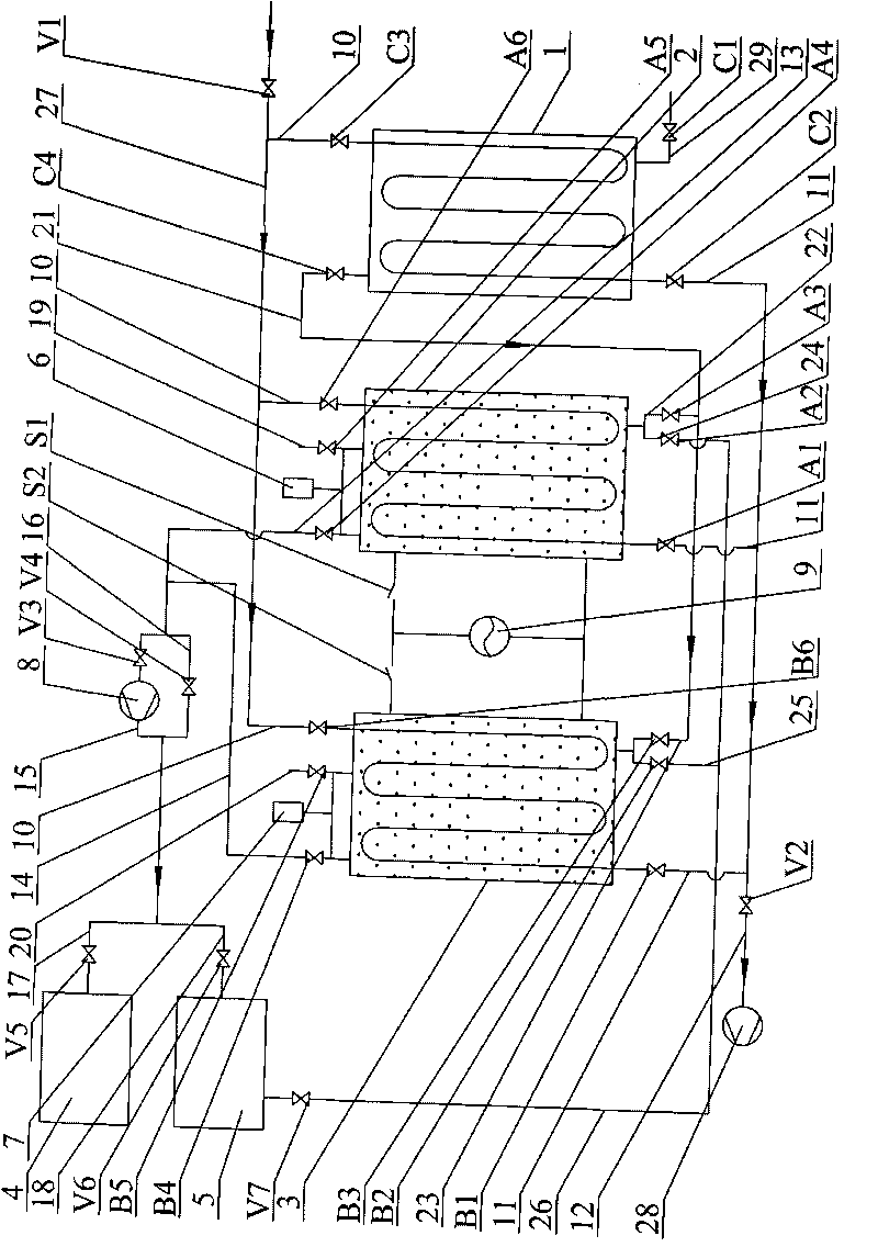
[0019] Specific implementation mode one: combine figure 1 Describe this embodiment, the temperature-lowering adsorption and low-voltage electric desorption of this embodiment captures CO 2 The method includes the following steps:

[0020] Step 1, flue gas cooling: flue gas in coal-fired power plants is removed by SO 2 and NO X Afterwards, the temperature drops to between 50°C and 60°C, and the above-mentioned cooled flue gas is passed into the heat exchanger 1 and exchanged with low-temperature tap water, so that the temperature of the flue gas passed into the heat exchanger 1 is reduced to 20°C. Between ℃-30℃ (because CO 2 The critical temperature of the adsorbent is below 31°C, and the adsorption capacity of the adsorbent is greater, and the lower the temperature, the better the CO 2 The greater the adsorption capacity, but at the same time the low temperature adsorbs N on the adsorbent 2 is also beneficial, so in order to obtain a high concentration of CO 2 , the adso...

specific Embodiment approach 2

[0028] Specific implementation mode two: combination figure 1 Describe this embodiment, this embodiment also includes step 21 between step 2 and step 3 in the next adsorption-desorption cycle process of the first adsorption-desorption tower 2: that is, CO 2 Purging step: the mole percentage stored in the buffer tank 5 in the last adsorption-desorption cycle reaches 80%-85% CO 2 Pass into the first adsorption-desorption tower 2 from bottom to top, and replace part of the N in the free space in the first adsorption-desorption tower 2 2 , when the first gas analyzer 6 shows that the CO at the flue gas outlet of the first adsorption-desorption tower 2 The mole percentage reaches the CO at the flue gas inlet of the first adsorption-desorption tower 2 When the concentration is 40%-50%, the process ends, and the next step, namely step three, is carried out.

[0029] During the adsorption process of the first adsorption-desorption tower 2, there is not only CO in the adsorption pha...

specific Embodiment approach 3

[0031] Specific implementation mode three: combination figure 1 Describe this embodiment, a kind of low-temperature adsorption and low-voltage electric desorption of this embodiment to capture CO 2 The system consists of heat exchanger 1, first adsorption-desorption tower 2, second adsorption-desorption tower 3, gas collection tank 4, buffer tank 5, first gas analyzer 6, second gas analyzer 7, vacuum pump 8, AC power supply 9, first switch S1, second switch S2, first valve C3, second valve A6, third valve B6, fourth valve C2, fifth valve A1, sixth valve B1, seventh valve A4, Eighth valve B4, ninth valve V3, tenth valve V4, eleventh valve V5, twelfth valve V6, thirteenth valve A3, fourteenth valve A2, fifteenth valve B3, sixteenth valve B2, Seventeenth valve C4, eighteenth valve V7, nineteenth valve A5, twentieth valve B5, three water inlet pipes 10, three water outlet branch pipes 11, main water outlet pipe 12, first flue gas pipe 13, second flue gas pipe 14. The third flue ...


PUM


Abstract

The invention relates to a method and a system for acquiring CO2 by temperature-lowering absorption and low-voltage desorption, in particular to a method and a system for captauring CO2 by a method of absorption and desorption, which overcomes the defects of difficult control, large energy consumption of the warming voltage-varying desorption method adopted by power plants to capturing CO2 and the defects of toxic and hazardous gas generated during capturing CO2 by chemisorption method. The method comprises temperature reduction by flue gases, communicating absorption of a first absorption and desorption tower, communicating absorption of a second absorption and desorption tower, and electrified temperature-increasing desorption, purification and temperature reduction of the first the absorption and desorption tower, CO2 gas purging, electrified temperature-increasing desorption, purification and temperature reduction of the second absorption and desorption tower, and communicating absorption of the first the absorption and desorption tower during a next absorption and desorption circulating process. In the system, the first and the second absorption and desorption towers are connected with an alternating current power supply through a first switch and a second switch, and the alternating current power supply is connected with the first and the second absorption and desorption towers. In the utility model, a physical adsorption method is adopted, thereby avoiding the generation of other toxic and hazardous gases by chemical methods. The method and the system are used for capturing CO2 in flue gases in coal industry works and power plants.

Description

technical field [0001] The invention relates to a method for capturing CO by means of adsorption and desorption 2 methods and systems. Background technique [0002] CO 2 It is the most important greenhouse gas and the main cause of the greenhouse effect. while in CO 2 Among the sources, thermal power plants are an important source of CO 2 Concentrated emission sources, about 1 / 3 of the world's CO 2 are emitted from power plants. Therefore, controlling and mitigating CO in electricity production 2 The emissions are of great significance to solving the problems of global warming and greenhouse effect. Therefore, the control of CO in the flue gas of thermal power plants, especially coal-fired power plants 2 Emissions are an effective measure to slow down the greenhouse effect. [0003] The main components of flue gas produced by power plant combustion are N 2 , O 2 , CO 2 , SO 2 and NO X , the main components after flue gas desulfurization and denitrification are ...

Claims


Application Information

Patent Timeline
IPC IPC(8): B01D53/04C01B31/20C01B32/50
CPCY02C10/08Y02A50/20Y02C20/40Y02P20/151
Inventor 谭羽非牛传凯
Owner HARBIN INST OF TECH
Learn More