Method utilizing medium with low melting point to realize fusion coupling of side face of optical fiber

A low melting point, welding technology, applied in the field of lasers, can solve the problems of fiber core beam transmission, fiber core laser power leakage, ablation and other problems that affect the coupling efficiency of pump light, achieve high coupling efficiency, avoid coupling efficiency reduction, and improve coupling efficiency effect

Inactive Publication Date: 2010-06-23
TSINGHUA UNIV
View PDF0 Cites 6 Cited by
  • Summary
  • Abstract
  • Description
  • Claims
  • Application Information

AI Technical Summary

Problems solved by technology

However, the optical glue commonly used in this technology will fail and ablate due to heat under high pump optical power injection, resulting in the inoperability of the side coupler
[0003] In this regard, Ou Pan et al. proposed the use of CO 2 The method of making a fusion-bonded side coupler with a laser, and carried out experimental research, to a certain extent solved the problem that the angle grinding-polishing coupling technology cannot withstand high pumping optical power density
However, in the fusion splicing process, the contact surfaces of the two coupled optical fibers need to be melted, and

Method used


Image

  • Method utilizing medium with low melting point to realize fusion coupling of side face of optical fiber
  • Method utilizing medium with low melting point to realize fusion coupling of side face of optical fiber
  • Method utilizing medium with low melting point to realize fusion coupling of side face of optical fiber

Examples


Embodiment 1

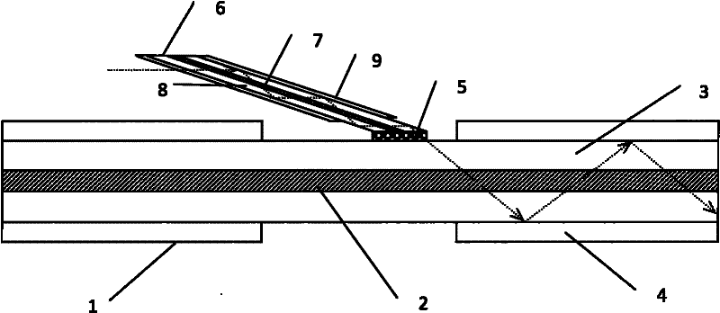
[0029] Such as figure 2 As shown, this embodiment is a coupler with a single point side fusion coupling. The coating (4) of a D-type double-clad fiber (1) with a diameter of 400 μm is removed with a knife for about 1 cm, exposing the inner cladding (3); the size of the pumping fiber (6) is 105 μm / 125 μm, and its After grinding and polishing the end face at an angle of about 10°, paste a small section of glass optical fiber (5) with a thickness of 1 μm and a diameter of 70 μm; stick the grinding and polishing slope of the pump optical fiber to the inner cladding of the double-clad optical fiber, and then use hydrogen The oxygen flame heats the glass optical fiber between the two, and squeezes the two sections of optical fiber again during the fusion splicing process, that is, the production of the single-point side fusion coupler is completed.

Embodiment 2

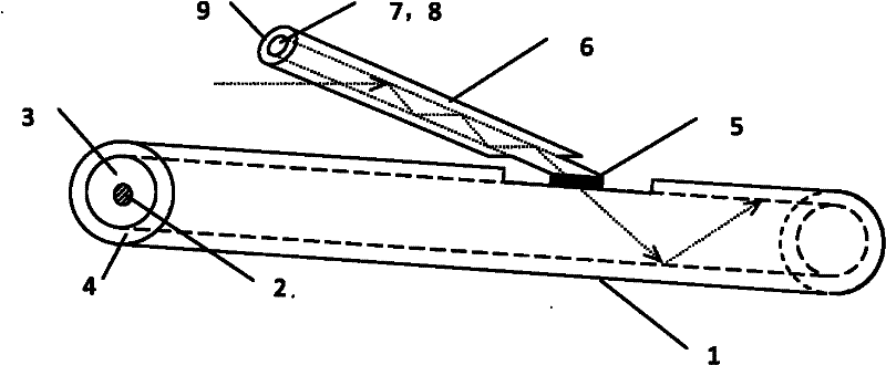
[0031] Such as image 3 As shown, this embodiment is a coupler with a single point side fusion coupling. The coating (4) of an octagonal double-clad fiber (1) with a diameter of 400 μm is removed with a knife for about 1 cm to expose the inner cladding (3); the size of the pumping fiber (6) is 105 μm / 125 μm, and the The end face is ground and polished according to an angle of about 10°, and the end face is covered with low-melting point glass powder (5); the grinding and polishing slope of the pump optical fiber is closely attached to the inner cladding of the double-clad optical fiber, and then heated with a microparticle blowtorch. The low-melting point glass between the two, the two sections of optical fiber are squeezed tightly again during the fusion splicing process, that is, the production of the single-point side fusion coupler is completed.

Embodiment 3

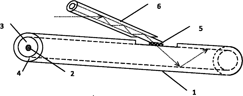
[0033] Such as Figure 4 As shown, this embodiment is a coupler with multi-point side fusion coupling. According to the method for embodiment 1, remove the coating (4) of the hexagonal double-clad fiber (1) with a diameter of 400 μm with fiber coating stripping pliers; 105 μm / 125 μm pumping fiber ( 6) Paste a low-melting quartz glass sheet (5) with a thickness of 0.5 μm and a diameter of 100 μm on the end face, and then stick it to the inner cladding (3) of the double-clad optical fiber (1), and use CO 2 Laser heating for welding. After completing the single-point side fusion, follow the same procedure to make a second coupling point at a certain distance from the first fusion zone. By analogy, a multi-point side fusion coupler can be obtained.


PUM

PropertyMeasurementUnit
Sizeaaaaaaaaaa
Diameteraaaaaaaaaa
Diameteraaaaaaaaaa

Abstract

The invention provides a method utilizing a medium with low melting point to realize fusion coupling of the side face of an optical fiber. In the method, small-angle end face grinding and polishing are carried out on a pumping optical fiber; the medium with low melting point is uniformly adhered on the ground and polished inclined plane, and is then adhered to the side plane of an inner cladding of the dual-cladding optical fiber; and then two optical fibers are fused together by the medium with low melting point in heating fusion zones such as oxyhydrogen flames, a CO2 laser device, propane gas, a fine-particle blow lamp and the like. The medium with low melting point is a fusion medium, the melting point of the fusion medium is lower than that of the optical fiber, and the fusion medium comprises glass with low melting point, quartz with low melting point, a glass optical fiber and the like. By adopting the medium with low melting point as the fusion medium, the method can finish fusion under the condition that the temperature is far lower than the melting point of the optical fiber without causing slight deformation of a fiber core structure of the optical fiber, thereby increasing the coupling efficiency of signal light.

Description

technical field [0001] The invention relates to a novel optical fiber side coupler, which is suitable for all-fiber high-power / energy optical fiber lasers and optical fiber amplifiers, and belongs to the technical field of lasers. Background technique [0002] In high-power fiber lasers and fiber amplifiers, the pump coupling technology is the core technology. The purpose is to couple tens of watts or even hundreds of watts of LD pump light power into the inner cladding of double-clad fibers with a diameter of only hundreds of microns. , to obtain high pump power. As an important pumping method, side-pump coupling makes good use of the characteristics of double-clad fibers. Among them, the optical fiber angle grinding and polishing coupling technology refers to the technology of grinding and polishing the end face of the pump fiber at an angle (inclined), and then coupling the end face with the side of the double-clad fiber. This technology has the characteristics of high ...

Claims


Application Information

Patent Timeline
IPC IPC(8): G02B6/255
Inventor 闫平巩马理郝金坪张海涛柳强黄磊
Owner TSINGHUA UNIV
Why Eureka
Try Eureka