
Battery electrode, preparation method thereof and vanadium redox flow battery comprising same

A battery electrode and electrode technology, which is applied in the direction of battery electrodes, electrode manufacturing, active material electrodes, etc., can solve the problems of conductive porous material matrix shedding, high cost of high-density graphite plates, and restrictions on the popularization of vanadium redox flow batteries. Effects of compactness, good reaction area, and good chemical reactivity

Active Publication Date: 2010-06-23
BYD CO LTD
View PDF0 Cites 5 Cited by
  • Summary
  • Abstract
  • Description
  • Claims
  • Application Information

AI Technical Summary

Problems solved by technology

At the same time, in the battery assembly process, in order to ensure the airtightness of the entire device, it is often necessary to apply a large pressure on both sides of the battery stack; however, due to the high brittleness of the graphite material itself, if the graphite plate is not uniformly stressed, it is easy to cause graphite cracked plate
Moreover, the composite structure between the conductive bipolar plate and the conductive porous material matrix will also produce a large contact resistance, and the problem of the conductive porous material matrix falling off is also very easy to occur during use.
In addition, the cost of high-density graphite plates as conductive bipolar plates is relatively high, which is not conducive to reducing the cost of electrodes
In summary, the above-mentioned shortcomings of the existing composite electrodes composed of conductive porous material matrix and conductive bipolar plates seriously limit the popularization of vanadium redox flow batteries, and it is imperative to develop new battery electrodes

Method used


Image

  • Battery electrode, preparation method thereof and vanadium redox flow battery comprising same
  • Battery electrode, preparation method thereof and vanadium redox flow battery comprising same
  • Battery electrode, preparation method thereof and vanadium redox flow battery comprising same

Examples


Embodiment approach

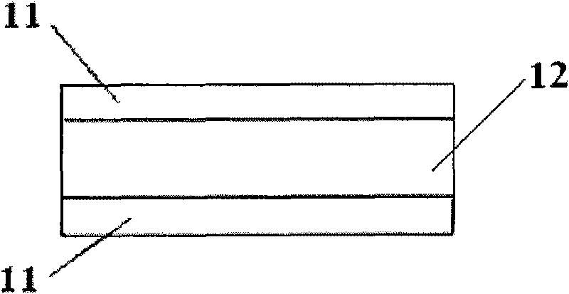
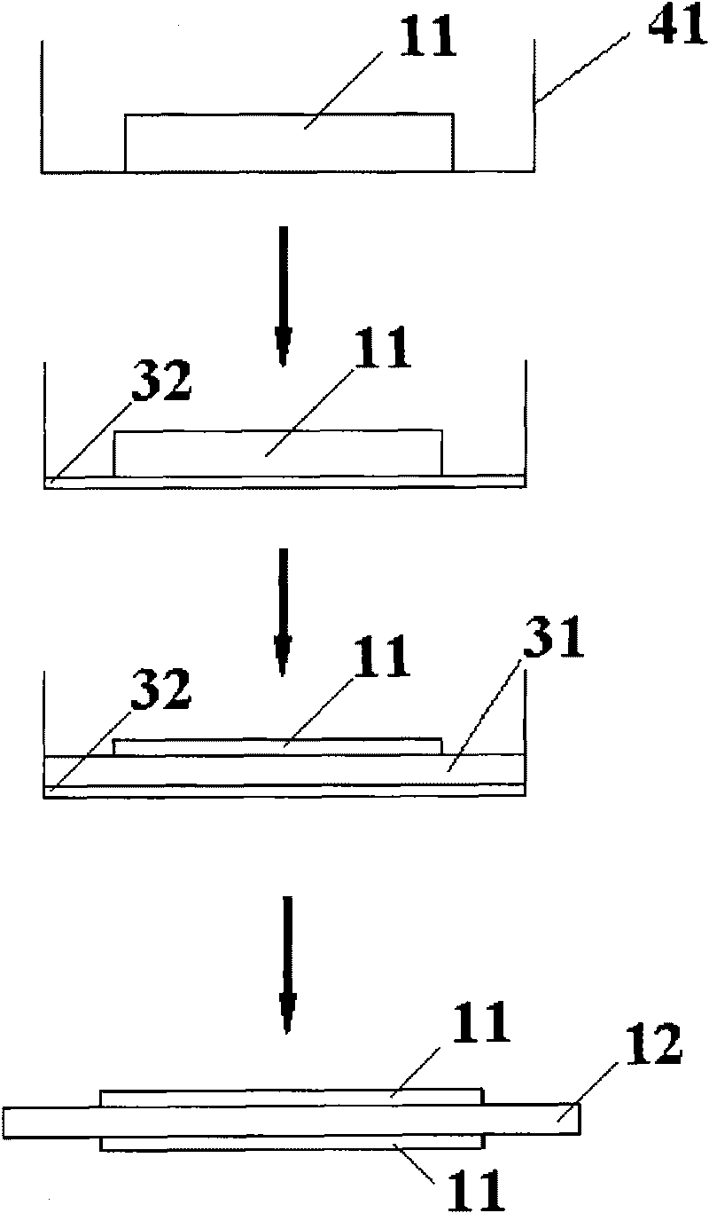
[0025] The method of making at least part of the polymerizable monomer enter the micropores of the partially conductive porous material matrix can be various methods that can be obtained by those skilled in the art in combination with the basic knowledge they have mastered. According to a method of the present invention In a preferred embodiment, the method of allowing at least part of the polymerizable monomer to enter the micropores of the partially conductive porous material matrix includes immersing one side of the conductive porous material matrix in a protective agent, allowing the protective agent to enter one side of the conductive porous material matrix. Then add polymerizable monomers to the conductive porous material matrix, so that at least part of the polymerizable monomers enter the micropores of the conductive porous material matrix, so that the upper layer of the obtained conductive porous material matrix, The middle layer and the lower three layers are respecti...

Embodiment 1

[0076] This example is used to illustrate the battery electrode of the present invention and its preparation method.

[0077] Equipped with exhaust device, and the size is 34mm×34mm×40mm Figure 4 Add graphite felt with a porosity of 85% in the shown flat-bottomed reactor, wherein the size of the graphite felt is 30mm × 30mm × 8mm; then add fully refined paraffin in the reactor as a protective agent, wherein the melting point of the paraffin is 62 ℃, use an external heater to heat the paraffin to melt it into a liquid state, and soak the graphite felt for 3 minutes to control the depth of the melted paraffin to 2 mm; then remove the heater and gradually lower the temperature to solidify the paraffin into a solid. Then, inject a mixture containing 5% by weight of azobisisobutyronitrile and 95% by weight of styrene monomer into the reactor containing the protective agent and graphite felt, and soak the graphite felt for 6 minutes to control the mixture containing styrene monomer...

Embodiment 2

[0079] This example is used to illustrate the battery electrode of the present invention and its preparation method.

[0080] Equipped with pumping and exhaust devices, and the size is 34mm×34mm×40mm Figure 4 Graphite felt with a porosity of 85% is added in the shown flat-bottomed reactor, wherein the size of the graphite felt is 30mm × 30mm × 8mm; then polyethylene glycol is added to the reactor as a protective agent, wherein the polyethylene glycol The melting point of the polyethylene glycol is 66°C. Use an external heater to heat the polyethylene glycol to melt it into a liquid, and soak the graphite felt for 3 minutes, and control the depth of the melted polyethylene glycol to 2mm; then remove the heater and gradually lower the temperature , to solidify polyethylene glycol into a solid. Then, inject a mixture containing 8% by weight diisopropyl peroxydicarbonate and 92% by weight styrene monomer into the reactor containing the protective agent and graphite felt, and soa...


PUM

PropertyMeasurementUnit
Glass transition temperatureaaaaaaaaaa
Melting pointaaaaaaaaaa

Abstract

The invention relates to a battery electrode which comprises a conductive porous material basal body and a polymer, wherein at least the partial polymer is distributed in millipores of the partial conductive porous material basal body, and the conductive porous material basal body is divided into an upper layer, a lower layer and a middle layer with a liquid isolating action by the polymer distributed in the millipores of the partial conductive porous material basal body, wherein the content of the polymer in the middle layer accounts for more than 75wt% of the total content of the polymer in the conductive porous material basal body, and the content of the polymer in the upper layer and the lower layer accounts for less than 25wt% of the total content of the polymer in the conductive porous material basal body. The invention also provides a vanadium redox flow battery comprising the battery electrode, and because the contact resistance is eliminated, the vanadium redox flow battery has low internal resistance and high charge and discharge efficiency.

Description

technical field [0001] The invention relates to a battery electrode, a preparation method of the battery electrode and a vanadium redox flow battery including the battery electrode. Background technique [0002] Vanadium redox flow battery is a new environment-friendly energy storage system and efficient energy conversion device, which has the characteristics of large scale, long life, low cost, high efficiency, non-toxic and harmless, and environment-friendly. Vanadium redox flow batteries can be used as large-scale electric energy storage and high-efficiency conversion equipment in wind and solar power generation systems; they can also be used for peak-shaving and valley-filling and load balancing of the power grid, which can improve power quality and power station operation stability. [0003] The vanadium redox flow battery uses vanadium (V) ion solutions of different valence states as the active material of the battery reaction, and the positive electrode of the battery...

Claims


Application Information

Patent Timeline
IPC IPC(8): H01M4/86H01M4/88H01M4/02H01M4/04H01M8/18
CPCY02E60/12Y02E60/528Y02E60/10Y02E60/50
Inventor 张一帆葛菲
Owner BYD CO LTD
Learn More