Integrated optical waveguide gyroscope based on optical microcavity

A technology that integrates optical waveguides and optical microcavities, which is applied in the coupling of optical waveguides, Sagnac effect gyroscopes, etc., can solve the problems of fiber optic gyroscope performance, fiber ring quality limitation, and unfavorable fiber optic gyroscope applications. Light, reasonable structure and wide application range

Inactive Publication Date: 2010-08-04
ZHONGBEI UNIV
View PDF0 Cites 8 Cited by
  • Summary
  • Abstract
  • Description
  • Claims
  • Application Information

AI Technical Summary

Problems solved by technology

[0005] The present invention provides an integrated optical waveguide gyroscope based on an optical microcavity in order to solve the problems that the performance improvement of the existing optical fiber gyroscope is limited by the quality of the optical fiber ring and is not conducive to the application of the optical fiber gyroscope in the high-precision field.

Method used


Image

  • Integrated optical waveguide gyroscope based on optical microcavity
  • Integrated optical waveguide gyroscope based on optical microcavity
  • Integrated optical waveguide gyroscope based on optical microcavity

Examples


Embodiment Construction

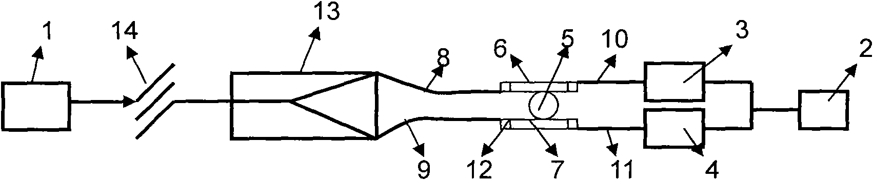
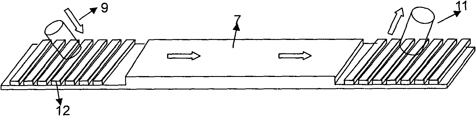
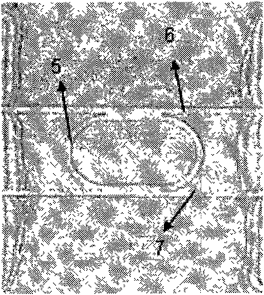
[0016] Such as figure 1 , 3 As shown, the integrated optical waveguide gyro based on the optical microcavity includes a light source 1, a beam splitter and a light detection device composed of a signal processing unit 2 and two photodetectors 3 and 4. The light source 1 is directly incident on the beam splitter The output port of the two photodetectors 3 and 4 is connected to the signal acquisition end of the signal processing unit 2, and includes an optical microcavity 5 processed on a semiconductor substrate by using MEMS processing technology, and an optical microcavity 5 arranged in parallel and symmetrically on the optical microcavity. The optical waveguides 6 and 7 on both sides of the cavity 5, and the two optical waveguides 6 and 7 respectively form an optical waveguide-microcavity coupling structure with the optical microcavity 5, and the optical microcavity 5 and the optical waveguides 6 and 7 are arranged between the beam splitter and the optical cavity. Between th...


PUM


Abstract

The invention relates to the optical field and the micro electromechanical field, in particular to an integrated optical waveguide gyroscope based on an optical microcavity, which solves the problems that the performance improvement of a traditional optical fiber gyroscope is restricted by the quality of an optical fiber ring, the optical fiber gyroscope is not beneficial to being applied to the high precision fields and the like. The integrated optical waveguide gyroscope comprises a light source, a beam splitter, an optical detection device as well as an optical microcavity and optical waveguides, wherein the optical detection device consists of a signal processing unit and two photo detectors, the optical microcavity is obtained through processing on a semiconductor substrate by using an MEMS (Micro-Electro-Mechanical System) processing technique, the optical waveguides are symmetrically arranged at two sides of the optical microcavity in parallel, the two optical waveguides and the optical microcavity respectively form an optical waveguide-microcavity coupling structure, two exit ports of the beam splitter respectively establish two incident light paths in one-to-one correspondence through an incident optical fiber and incident ends of the two optical waveguides and exit ends of the two optical waveguides respectively establish two exit light paths in one-to-one correspondence through an exit optical fiber and the input ends of the two photo detectors in the optical detection device. The invention has simple and reasonable structure, high flexibility and wide application range and can be suitably applied to the field of high precision measurement.

Description

technical field [0001] The invention relates to the field of optics and micro-electromechanical technology, in particular to an integrated optical waveguide gyroscope based on an optical microcavity. Background technique [0002] The gyroscope is the core component of the inertial system, which can accurately determine the orientation of moving objects. It is an inertial navigation instrument widely used in modern aviation, navigation, aerospace and defense industries. The traditional inertial gyroscope mainly refers to the mechanical gyroscope. The mechanical gyroscope has high requirements on the process structure, the structure is complex, and the measurement accuracy is restricted by many aspects. Since the 1970s, optical gyroscopes have become the main development of modern gyroscopes, including laser gyroscopes and fiber optic gyroscopes, both of which are based on the Sagnac effect discovered by French scientist G.Sagnac in 1913 (that is, in an arbitrary geometric sha...

Claims


Application Information

Patent Timeline
Patent Type & Authority Applications(China)
IPC IPC(8): G01C19/64G02B6/28G02B6/34
Inventor 刘俊张文栋闫树斌薛晨阳丑修建赵敏严英占石云波仝晓刚
Owner ZHONGBEI UNIV
Why Eureka
Try Eureka