Device for removing paraffin and washing well by gas heat carrier

A gas heat carrier and wax removal technology, which is used in isolation devices, cleaning appliances, wellbore/well components, etc., can solve the problems of difficult wax and scale cleaning, large emission pollution, low efficiency, etc., and achieves convenient fuel sources. , the effect of improving oil recovery and good application prospects

Inactive Publication Date: 2010-10-13
辽阳华路催化技术研发有限公司
View PDF0 Cites 4 Cited by
  • Summary
  • Abstract
  • Description
  • Claims
  • Application Information

AI Technical Summary

Problems solved by technology

The cost of using cooked oil as a heat carrier is too high
Using boilers to generate hot water to inject downholes has the disadvantages of low thermal efficiency and the use of a large amount of well washing fluid, which may cause damage to sensitive oil layers; this method requires large equipment, high energy consumption, low efficiency, and large emission pollution; compared with well pressure Oil wells with high wax content are difficult to operate; for oil wells with high wax content and heavy oil wells, it is more difficult to remove wax and scale

Method used


Image

  • Device for removing paraffin and washing well by gas heat carrier
  • Device for removing paraffin and washing well by gas heat carrier
  • Device for removing paraffin and washing well by gas heat carrier

Examples


example 1

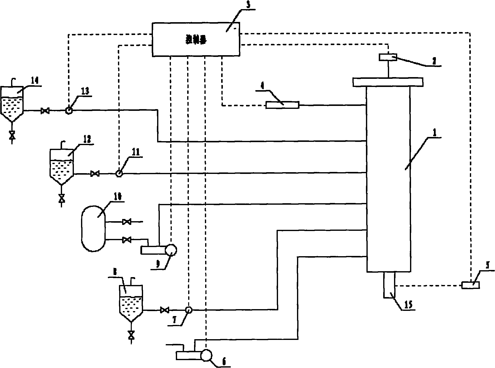
[0028] example 1: figure 1 Schematic diagram of wax removal and well cleaning device for gas heat carrier, including high temperature gas generator 1, igniter 2, controller 3, protection system 4, gas analysis system 5, air compressor 6, high pressure fuel injection pump 7, fuel tank 8, natural gas Compressor 9, natural gas storage tank 10, gasification water injection pump 11, gasification water tank 12, cooling water pump 13, cooling water tank 14, high temperature gas discharge port 15. Because most oil production wells have associated natural gas and its collection system, this device is designed with two sets of fuel systems, fuel oil and gas.

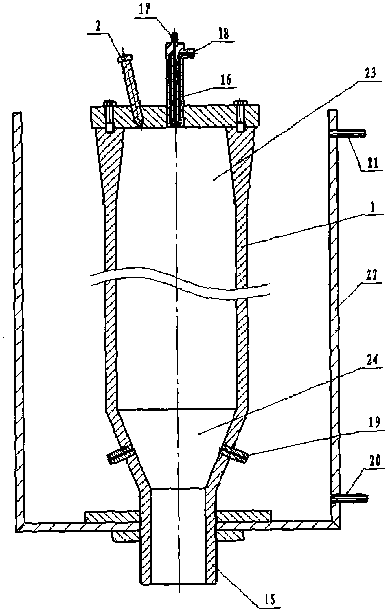
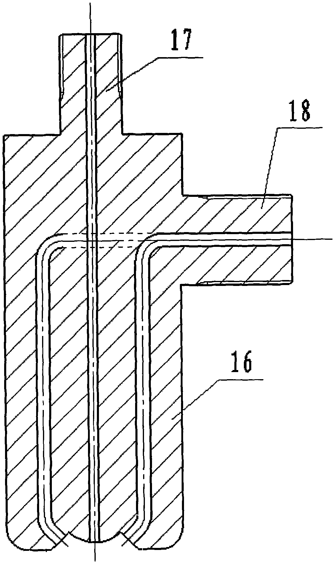
[0029] figure 2 It is a high-temperature gas generator, including gas generator body 1, igniter 2, air-fuel mixer 16, cooling water tank 22, cooling water inlet 21, cooling water outlet 20, combustion chamber 23, gasification chamber 24, gasification water spray Hole 19, gas nozzle 15. The high-temperature gas generator adopts...

example 2

[0032] Example 2 is basically the same as Example 1

[0033] Description of gas heat carrier wax removal and well washing device: gas heat carrier wax removal and well washing device, including high temperature gas generator 1, igniter 2, controller 3, protection system 4, gas analysis system 5, air compressor 6, high pressure jet Oil pump 7, fuel tank 8, natural gas compressor 9, natural gas storage tank 10, gasification water injection pump 11, gasification water tank 12, cooling water pump 13, cooling water tank 14, high temperature gas discharge port 15, cooling water tank 22, cooling water inlet 21. Cooling water outlet 20 , combustion chamber 23 , gasification chamber 24 , gasification water spray hole 19 , air-fuel mixer 16 including compressed air inlet 18 and fuel inlet 17 . The air-fuel mixer adopts the mixing method of double-sided 45-degree oblique blowing fuel. The diameter of the fuel port is (natural gas) 3mm, the diameter of the compressed air inlet is 2×6mm, a...


PUM


Abstract

The invention provides a device for removing paraffin and washing well. The device comprises a high-temperature gas generator, and an air compressor, a high-pressure fuel injection pump, a gas analysis system, a high-pressure fuel injection pump, a gasification water injection pump and a cooling water pump which are controlled by a controller, wherein the high-temperature gas generator comprises a cylinder block, a cooling water tank, an air-fuel mixer, a compressed air inlet, a cooling water inlet, a cooling water outlet, an igniter, a combustion chamber, a gasification blending chamber, a gasification water injection inlet and a high-temperature gas spout formed at the lower end of the gasification blending chamber. The device has the advantages of capability of burning diesel oil and accompanying natural gas generated by burning oil wells directly, environmental protection, energy conservation, low operation cost, convenient fuel sources, small volume, light weight, flexibility andconvenience, and excellent application prospect in the aspects of paraffin removal and dirt washing of the oil wells.

Description

Technical field: [0001] The invention provides a well flushing device for removing wax deposits and scaling in oil production well pipes. Background technique: [0002] In the process of oil exploitation, wax and scale often form in the production well pipe, which gradually reduces the inner diameter of the oil pipe, affects the oil production efficiency, and reduces the well fluid output; at the same time, the pressure in the oil pipe increases, which increases the load of the oil pump and shortens the service life of the oil pump. The existing wax removal technology mainly adopts mechanical wax removal and thermal wax removal. Mechanical wax removal is not thorough and affects oil well production. Thermal wax removal generally uses a boiler to heat the heat carrier, such as hot oil, hot water, etc., to bring heat energy into the wellbore, increase the temperature of the wellbore, and make it exceed the melting point of the wax, so that the wax can be melted to achieve the ...

Claims


Application Information

Patent Timeline
Patent Type & Authority Applications(China)
IPC IPC(8): E21B37/00E21B36/02
Inventor 侯宇
Owner 辽阳华路催化技术研发有限公司
Why Eureka
Try Eureka