Method for preparing microfluidic chip probe array for use in biochip analysis

A technology of microfluidic chips and probe arrays, applied in biochemical equipment and methods, measurement/testing of microorganisms, bioreactors/fermenters for specific purposes, etc., can solve the limitation of probe number and density, probe Problems such as low temperature resistance, experimental operation, system integration, and difficulty in developing new applications can achieve the effects of speeding up production, reducing dependence, and reducing processing costs.

Active Publication Date: 2010-10-20
成都艾迪恩生物科技有限公司 +1
View PDF4 Cites 14 Cited by
  • Summary
  • Abstract
  • Description
  • Claims
  • Application Information

AI Technical Summary

Problems solved by technology

Because the probes are not resistant to high temperature, in these methods, the microfluidic chip cannot be bonded at high temperature, which brings great difficulties to chip production, experimental operation, system integration and development of new applications; on the other hand, manual Align the microchannel and the probe array. A large number of repeated probes must appear in the probe array to ensure that the required probes are contained in the microchannel. The number and density of the probes are greatly limited, and the carrier cannot be effectively used. surface

Method used


Image

  • Method for preparing microfluidic chip probe array for use in biochip analysis
  • Method for preparing microfluidic chip probe array for use in biochip analysis
  • Method for preparing microfluidic chip probe array for use in biochip analysis

Examples


Embodiment 1

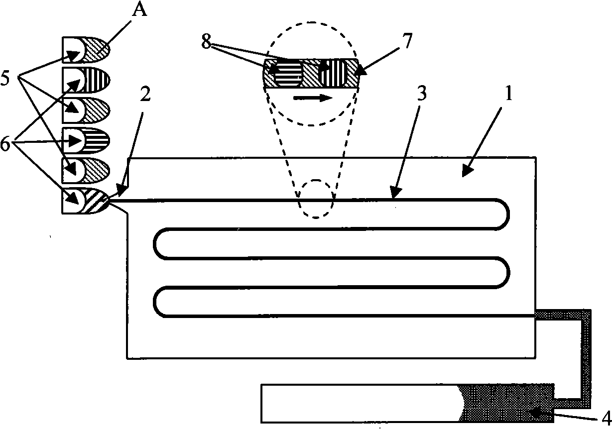
[0023] see figure 1 , the microchannel 3 of the chip 1 is in the shape of a coil, and its inlet 2 is processed into a needle shape, which is inserted into a small test tube A for storing liquid. Small liquid storage test tubes A are arranged at intervals and are respectively equipped with mineral oil 5 and probe solution 6 . The outlet of the microchannel is connected with a horizontal liquid reservoir 4 , and gravity drives the liquid to flow, so that the mineral oil 7 carries the probe droplet 8 to flow in the microchannel 3 . After the flow reaches the predetermined position, the flow is stopped and the immobilization reaction of the probes is carried out to complete the processing of the probe array.

[0024] Figure 6 It is the fluorescent signal intensity obtained by fixing nucleic acid probes of different concentrations for 30 minutes. The probe contains 20 bases, 3' labeled with FITC, 5' labeled with amino groups, through chemical reactions with free aldehyde groups ...

Embodiment 2

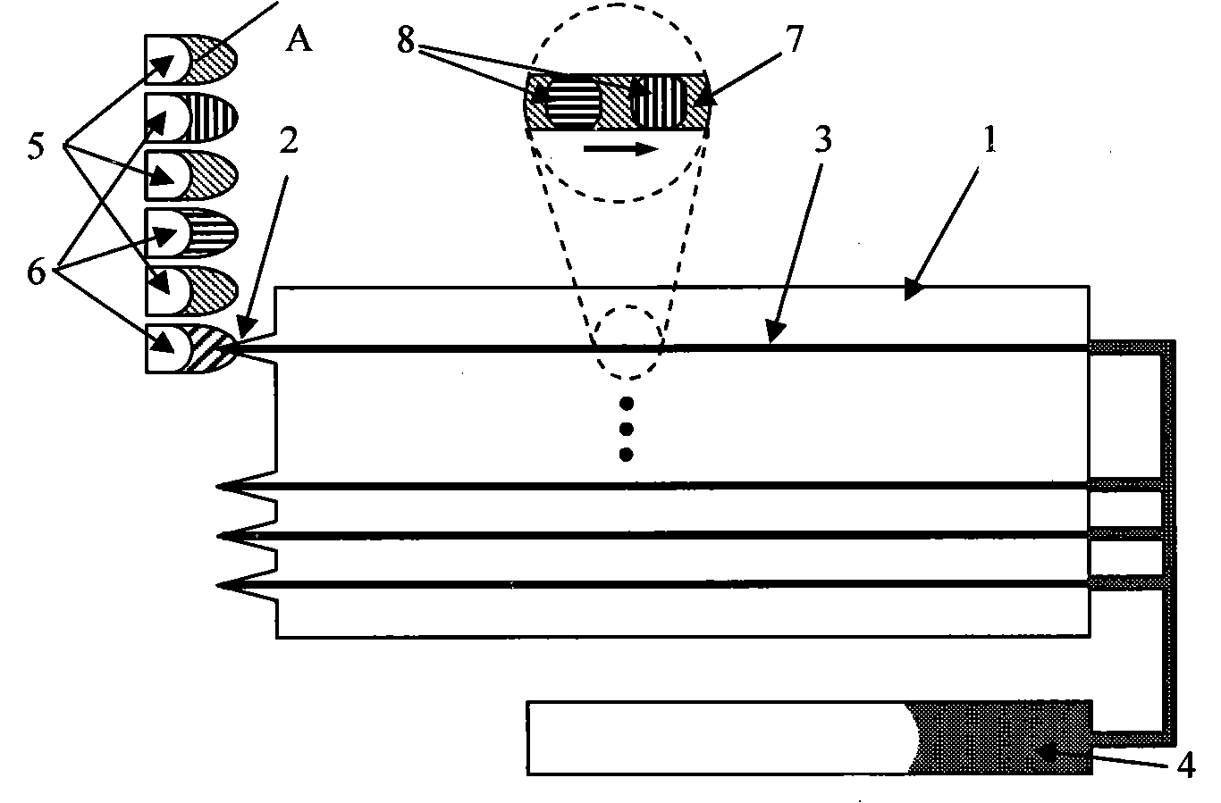
[0026] see figure 2 The microchannel 3 of the chip 1 is one or more parallel channels, each channel is processed with an inlet and an outlet, and multiple parallel probe arrays are processed for multiple parallel biochip analysis. exist figure 2 , the other flags are the same as figure 1 same.

Embodiment 3

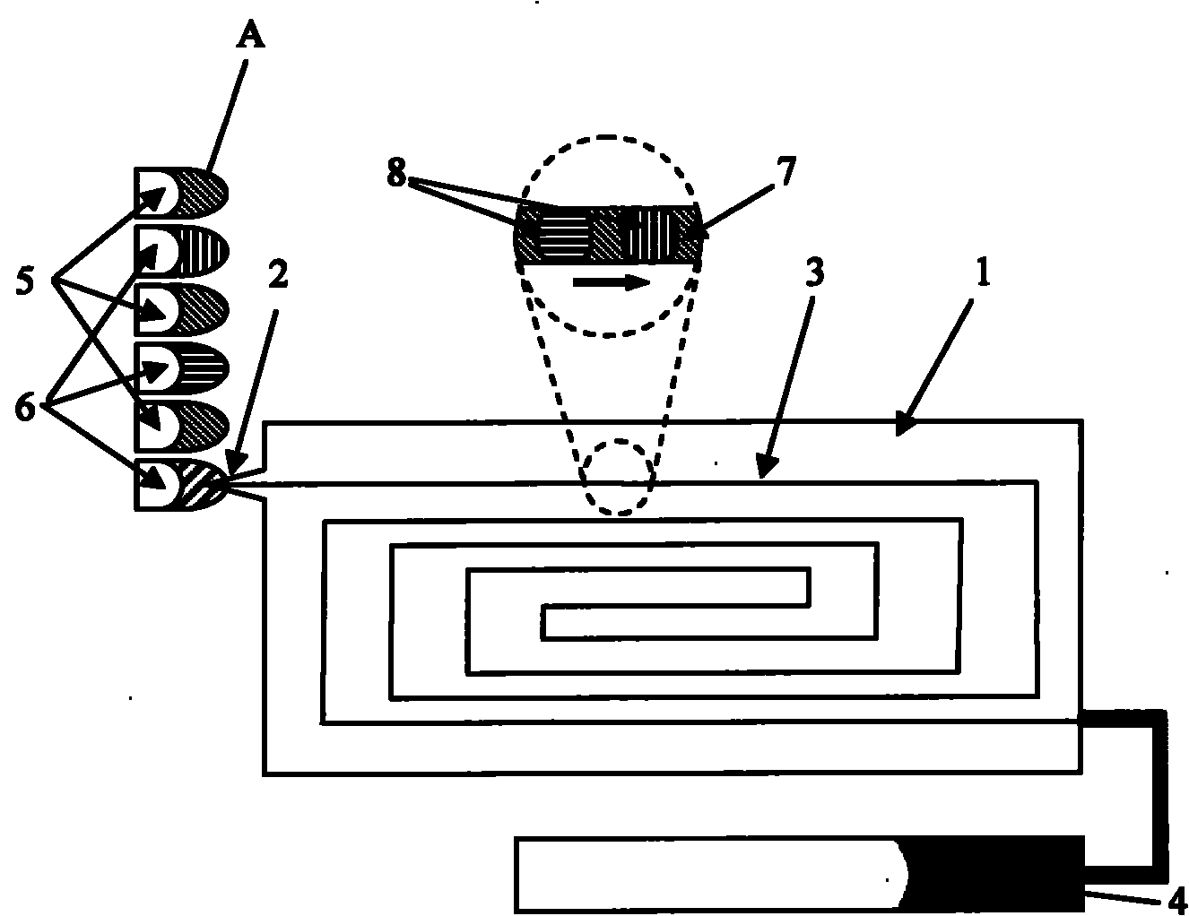
[0028] see image 3 , the microchannel 3 is in a spiral shape and is used for processing the probe array. exist image 3 , the other flags are the same as figure 1 same.


PUM

PropertyMeasurementUnit
sizeaaaaaaaaaa

Abstract

The invention discloses a method for preparing a microfluidic chip probe array for use in biochip analysis, which relates to biochips. The method comprises: introducing solution to a micro channel; arranging storage tanks or small test tubes, which contain mineral oil or other solvents insoluble in water and probe solution, at intervals for supplying liquid, and realizing a liquid drop sequence of 'mineral oil, probe solution, mineral oil, probe solution and mineral oil' in the micro channel by replacing the supplied liquid at the entrance of the micro channel, wherein the mineral oil serves as a carrier current and the probe solution serves as a drops flowing in the carrier current; and after the probe liquid drop sequence flows to a preset position, making the probe liquid drop sequence stop flowing to allow the probes in the liquid drops to emit light automatically or to be immobilized on the inside surface of the micro channel by the reaction or absorption initiated by light, electricity and magnet in the outside, discharging the mineral oil and the probe liquid drops after the immobilization reaction is finished and washing with buffer liquid to finish the whole step.

Description

technical field [0001] The invention relates to a biochip, in particular to a method for preparing a microfluidic chip probe array for biochip analysis. Background technique [0002] Biochips immobilize a large number of biomolecules or materials (such as nucleic acid fragments, proteins, drugs or receptors, cells or tissues, etc.) Carry out specific adsorption or reaction to realize the detection of sample information. Thousands of reactions are performed simultaneously on a single chip, with the capability of massively parallel analysis. Biochips are generally processed on carrier materials such as glass wafers, silicon wafers, and nylon membranes. The method of making probe arrays is mainly the spotting method (Schena M, Shalon D, Davis R W. et al. Science., 1995, 20: 467 -470) and in-situ synthesis (Fodor S P A, Read J L, Pirrung M C, et al.Science, 1991, 251: 767-773), the spotting method is to use a spotting instrument to spot the probe on the surface of the carrier ...

Claims


Application Information

Patent Timeline
Patent Type & Authority Applications(China)
IPC IPC(8): C12M1/34C12Q1/68G01N21/64G01N35/00
Inventor 陈宏瞿祥猛
Owner 成都艾迪恩生物科技有限公司
Why Eureka
Try Eureka