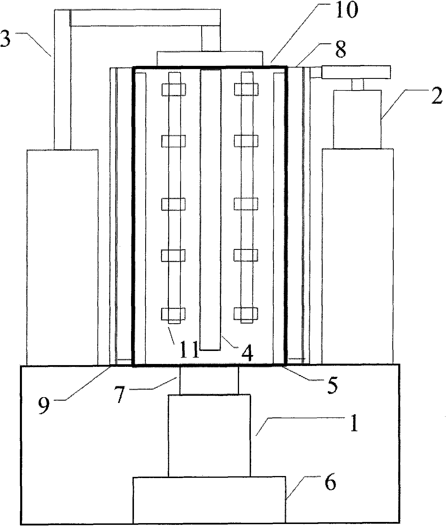
Hollow cathode sputtering ion plating device
A cathode sputtering and ion plating technology, applied in the direction of sputtering plating, ion implantation plating, vacuum evaporation plating, etc., can solve problems such as difficulties, inability to meet thick coating requirements, low deposition rate, etc., and achieve uniform distribution , Improve the effect of ion plating, improve the effect of coating uniformity
- Summary
- Abstract
- Description
- Claims
- Application Information
AI Technical Summary
Problems solved by technology
Method used
Image

Examples
Embodiment 1
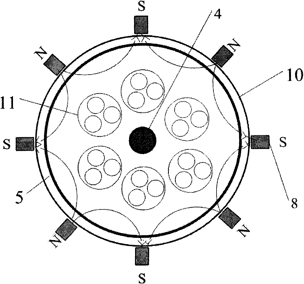
[0026]Embodiment 1: Under the condition of 0.02Pa and negative 150V bias, a metal Cr arc target controlled by a magnetic field is used to prepare a pure Cr metal transition layer; then nitrogen gas is introduced, and the air pressure is maintained at 0.5Pa, and the magnetron chromium target on the furnace wall is opened. CrN is generated by the reaction of nitrogen gas and Cr sputtered from the target surface. The nitrogen gas flow rate is 50-200 sccm, the argon gas flow rate is 70-80 sccm; the current of the magnetron metal target on the furnace wall is 150-180A. The center rotating target current is 80-100A.
[0027] The above-mentioned glow discharge cleaning is carried out at 350-400°C in an argon environment; after the glow cleaning is completed, the cathode arc discharge of the metal Cr target is carried out under the condition of 0.02Pa, and the deposition thickness of the metal transition layer is 100-200 nanometers; the CrN coating The layer thickness is 20-30 micron...
Embodiment 2
[0028] Embodiment 2: under the condition of 0.02Pa, negative 200V bias, utilize the metal Ti electric arc target of magnetic field control to prepare pure Ti metal transition layer; Pass into nitrogen then, air pressure keeps 0.8Pa, open the magnetron Ti target on the furnace wall, Nitrogen gas is used to react with Ti sputtered from the target surface to form TiN. The nitrogen gas flow rate is 100-120 sccm, the argon gas flow rate is 80-90 sccm; the current of the magnetron metal target on the furnace wall is 130-150A. The center rotating target current is 60-80A.
[0029] The above-mentioned glow discharge cleaning is carried out at 330-350°C in an argon environment; after the glow cleaning is completed, the cathode arc discharge of the metal Ti target is carried out under the condition of 0.02Pa, and the deposition thickness of the metal transition layer is 200-300 nanometers; the TiN coating The layer thickness is 30-40 microns. The preparation temperature is 400-450°C, ...
Embodiment 3
[0030] Embodiment 3: under the condition of 0.05Pa, negative 300V bias, utilize the metal Zr arc target of magnetic field control to prepare pure Zr metal transition layer; Pass into nitrogen then, air pressure keeps 0.6Pa, open the magnetron Zr target on the furnace wall, ZrN is generated by the reaction of nitrogen gas and Zr sputtered from the target surface. The flow rate of nitrogen gas is 100-120 sccm, the flow rate of argon gas is 100-140 sccm; the current of the magnetron metal target on the furnace wall is 160-180A. The center rotating target current is 100-120A.
[0031] The above-mentioned glow discharge cleaning is carried out at 380-420°C in an argon environment; after the glow cleaning is completed, the metal Zr target cathode arc discharge is carried out under the condition of 0.02Pa, and the deposition thickness of the metal transition layer is 200-300 nanometers; ZrN coating The layer thickness is 40-50 microns. The preparation temperature is 400-450°C, and ...
PUM
| Property | Measurement | Unit |
|---|---|---|
| Deposition thickness | aaaaa | aaaaa |
| Deposition thickness | aaaaa | aaaaa |
| Deposition thickness | aaaaa | aaaaa |
Abstract
Description
Claims
Application Information
PatSnap Eureka turns technology decisions into work you can execute. Powered by our Innovation Knowledge Graph, it runs expert workflows across engineering, life sciences, materials and intellectual property. Get your review-ready output in minutes.


