New energy-saving cleaning technology and device of light oil rail tanker, liquefied gas tanker or ammonia tanker

A technology for liquefied gas tanks and oil tank trucks, which is applied in the direction of cleaning hollow objects, cleaning methods and appliances, chemical instruments and methods, etc., and can solve problems such as failure to eliminate hidden dangers of accidents, no recovery device, long cleaning cycle, etc., to reduce labor The effect of intensity, simple method and ingenious structure

Inactive Publication Date: 2010-11-17
昆明铁路局科学技术研究所
View PDF4 Cites 13 Cited by
  • Summary
  • Abstract
  • Description
  • Claims
  • Application Information

AI Technical Summary

Problems solved by technology

However, there are various cleaning tasks for railways that are completed in sections, and the cleaning cycle is long; there is no recovery device for various sewage generated during cleaning; all special heating

Method used


Image

  • New energy-saving cleaning technology and device of light oil rail tanker, liquefied gas tanker or ammonia tanker
  • New energy-saving cleaning technology and device of light oil rail tanker, liquefied gas tanker or ammonia tanker
  • New energy-saving cleaning technology and device of light oil rail tanker, liquefied gas tanker or ammonia tanker

Examples


Embodiment 1

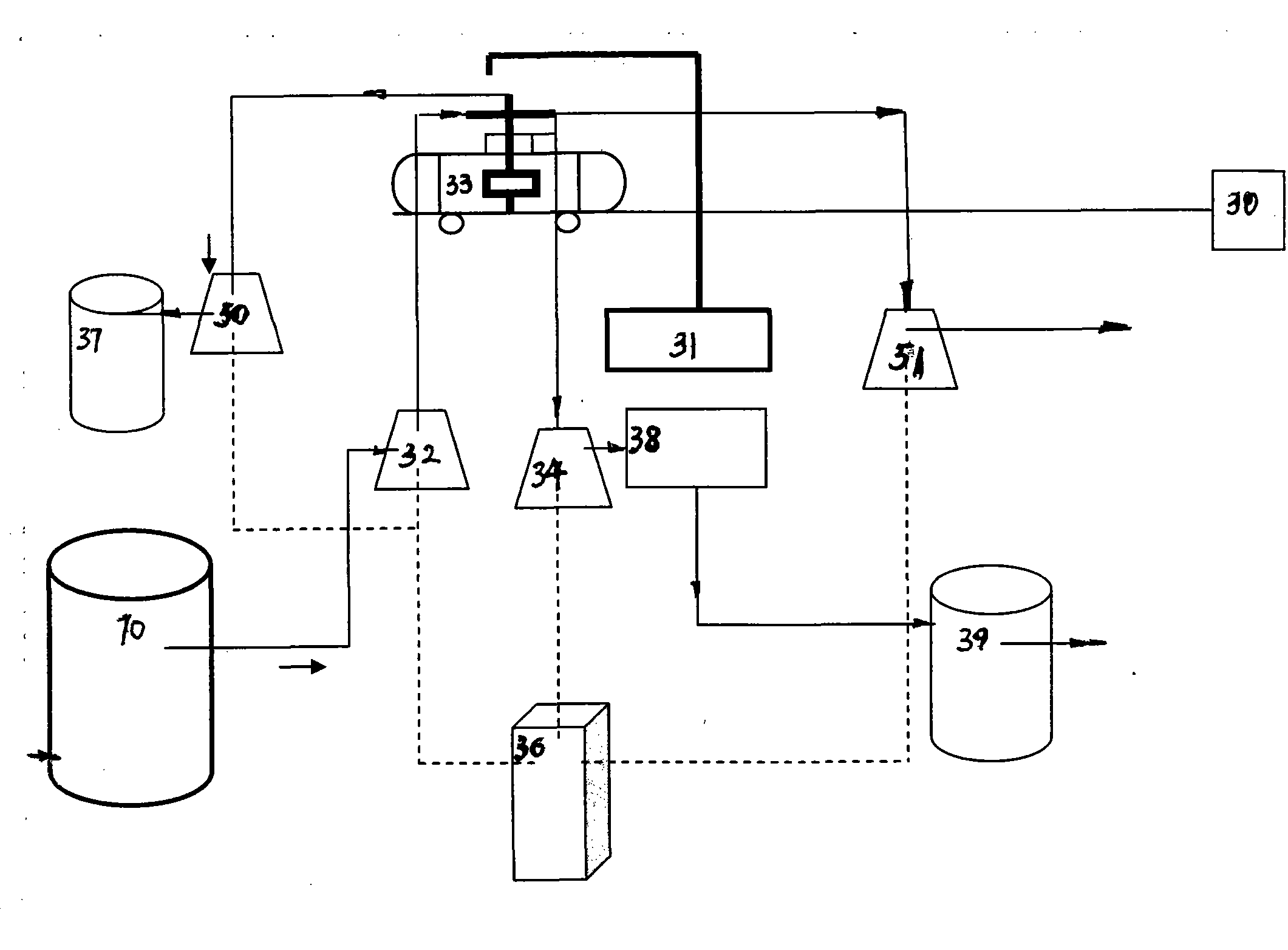
[0036] Embodiment 1 (light oil, such as figure 2 Shown): a row of light oil tank cars ready to be cleaned is towed by the traction device 30 to the line to be washed outside the tank washing station, and the light oil tank cars are towed by the traction device 30 to the cleaning platform of the light oil tank cars , after the hoisting device 31 is aligned with the opening on the upper part of the first section of light oil tanker, the hoisting device 31 will lift the water pipe on the centrifugal pump 32, the three-dimensional tank washer 33, the suction pipe on the self-priming pump 34, the vacuum pump 50 and the vacuum pump The suction pipe on the 51 is hoisted in place at one time, connects respectively the suction pipe in the centrifugal pump 32, the suction pipe of the self-priming pump 34 and the suction pipe in the vacuum pump 50,51, and the preparatory work is just in order.

[0037] First start the control button of the control device 36 vacuum pump 50, the vacuum pu...

Embodiment 2

[0039] Embodiment 2 (liquid ammonia, such as figure 2 As shown) a line of liquid ammonia tank cars to be cleaned is towed by the traction device 30 to the line to be washed outside the tank washing station, the liquid ammonia tank cars are towed by the traction device 30 to the liquid ammonia tank car cleaning station, and the hoisting device 31 is aligned with the mouth of the liquefied gas tank car Finally, the hoisting equipment 31 lifts the water pipe on the centrifugal pump 32, the three-dimensional tank washing device 33, the suction pipe on the self-priming pump 34, and the suction pipe on the vacuum pump 50 and 51 respectively;

[0040] First start the control device 36 to synchronously clean the suction control button, first use the centrifugal pump 50 to pressurize the dilute liquid ammonia in the liquid ammonia recovery device 37, and the three-dimensional tank washer 33 can rotate and revolve, and the water pressure of the jet can be within 360°. 1.0-1.5Mpa dilute...

Embodiment 3

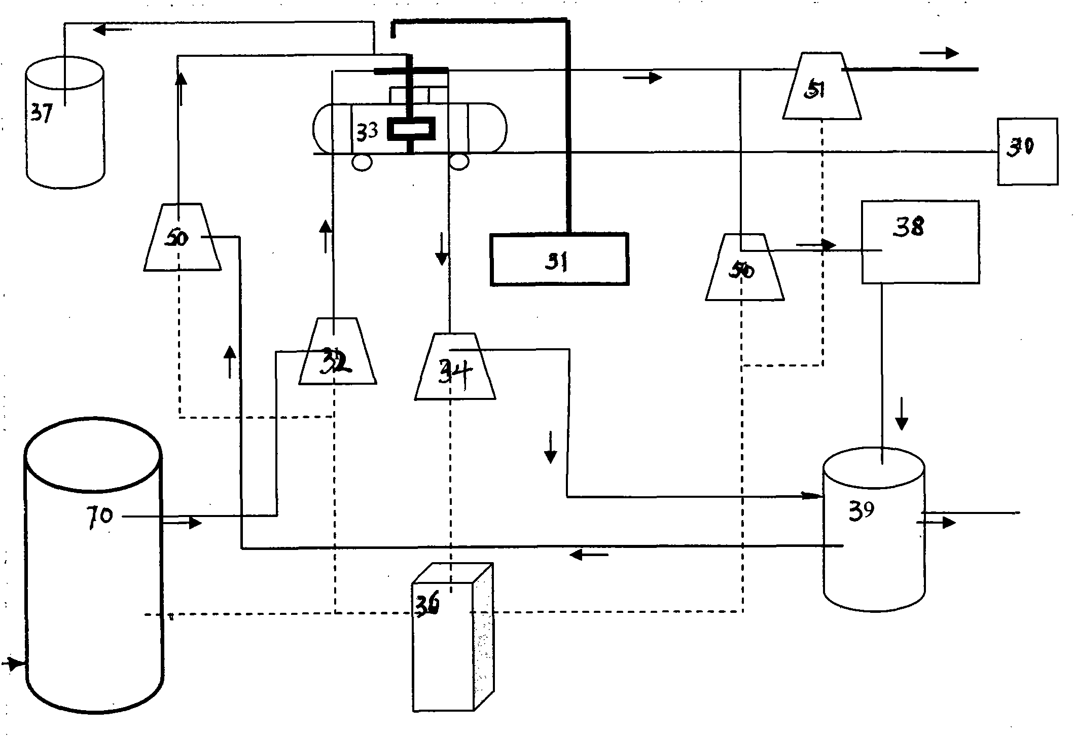
[0042] Embodiment 3 (liquefied gas, such as image 3 Shown) a row of liquefied gas tank cars to be cleaned is towed by the traction device 30 to the line to be washed outside the tank washing station of the present invention, the liquefied gas tank cars are towed by the traction device 30 to the liquefied gas tank car cleaning station, and the hoisting device 31 is aligned with the liquefied gas After the tank car entrance, hoisting equipment 31 lifts the water pipe in the centrifugal pump 32, the suction pipe in the self-priming pump 34, and the suction pipe in the vacuum pump 51 once to hoist in place.

[0043] First start the centrifugal pump 50 to suck the reclaimed water to the liquefied gas tanker, recover the residual liquefied gas through the recovery device 37 for liquefied liquefied gas, and complete the liquefied gas recovery work after 2-3 hours; then start the vacuum pump 51 suction control button , the residual liquefied gas is vacuum-sucked, the residual liquefi...


PUM


Abstract

The invention relates to a new environmentally friendly and energy-saving cleaning technology and device of light oil rail tankers, liquefied gas tankers or ammonia tankers, which adopt the jet cleaning technology, the hot water supply technology and the waste oil/gas recovery technology. The invention belongs to the cleaning equipment of the railway tank car. The technology of the invention is as follows: solar energy is fully utilized, an air heat pump is used to obtain the heat energy of the environment; the obtained 60-90 DEG C hot water is used for cleaning while a three-dimensional tank washer, a centrifugal pump and a self-sucking pump are used to perform cleaning, suction, vacuum suction and oil-water separation at the same time; a waste oil/gas recovery device and an oil-water separation device are used to recover and utilize the waste oil and gas in various light oil rail tankers, liquefied gas tankers or ammonia tankers through the oil-water separation technology. Therefore, the cleaning efficiency is increased and the labor intensity is reduced.

Description

technical field [0001] The invention relates to a new process and equipment for energy-saving cleaning of light oil tank cars, liquefied gas tank cars or ammonia gas tank cars transported by railways by using jet cleaning technology, hot water supply technology, waste oil / waste gas recovery technology and oil-water separation technology. The utility model belongs to the field of cleaning equipment for railway tank cars. Background technique [0002] Every year in our country, millions of tank cars need to be cleaned regularly. Common tank car cleaning methods include dry work, wet cleaning, steam fumigation and chemical methods. The cleaning efficiency of the dry cleaning method is low, and the workman's labor load is large and is not used. The wet cleaning method consumes a lot of water resources, and it is not often used if the cleaning is not clean enough. Chemical cleaning requires chemical cleaning agents, which will cause environmental pollution in large quantities....

Claims


Application Information

Patent Timeline
IPC IPC(8): B08B9/093
Inventor 杨贵荣曾进忠王耕捷官崇祺郭志强张涛
Owner 昆明铁路局科学技术研究所
Why Eureka
Try Eureka