Method of manufacturing gravure plates for offset printing

A printing plate and gravure technology, applied in the field of preparing gravure printing plates for offset printing, to achieve the effects of high graphic accuracy, excellent thickness uniformity and excellent durability

Inactive Publication Date: 2010-12-15
LG CHEM LTD
View PDF0 Cites 3 Cited by
  • Summary
  • Abstract
  • Description
  • Claims
  • Application Information

AI Technical Summary

Problems solved by technology

Due to the above problems, the gravure offset printing method has a disadvantage in that the intaglio glass plate must be frequently replaced with a new intaglio glass plate in the offset printing method using the intaglio glass plate

Method used


Image

  • Method of manufacturing gravure plates for offset printing
  • Method of manufacturing gravure plates for offset printing
  • Method of manufacturing gravure plates for offset printing

Examples


preparation example Construction

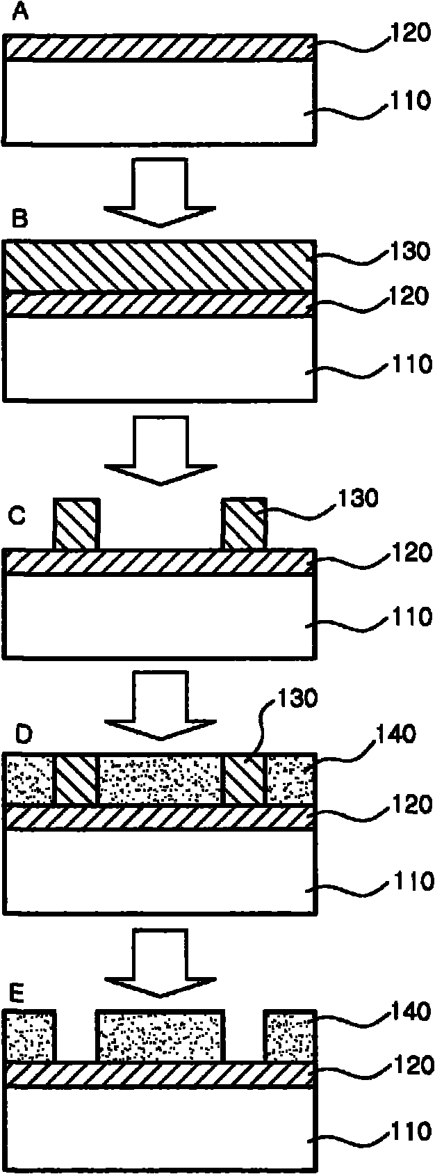
[0019] A method for preparing a gravure printing plate for offset printing according to an exemplary embodiment of the present invention is characterized in that the method includes the steps of: coating a glass substrate with copper metal; forming a photoresist film on the coated copper metal; The desired photoresist pattern is formed by exposing the photoresist film to light and then developing the photoresist film to remove the photoresist from some of the photoresist film; plating nickel to the areas where the photoresist was removed; and removing the remaining photoresist and polish the nickel-plated surface.

[0020] figure 2 is a diagram showing a method of preparing a gravure printing plate for offset printing according to an exemplary embodiment of the present invention. In the following, refer to figure 2 Each step of the method is described in more detail.

[0021] (1) Operation of coating copper metal (A)

[0022] First, a glass substrate is coated with coppe...

Embodiment

[0045] Copper metal was sputtered onto a glass substrate (ie, soda lime glass, available from KCC) at a pressure of 3 mTorr and a power of 5 kW, thereby forming a copper coating film with a thickness of 200 nm.

[0046] A negative type dry film resist (DFR, available from KOLON) was adhered to the copper coating film, and then irradiated for 2 to 10 seconds through a photomask using i-line ultraviolet rays with a wavelength of 365 nm . Next, add 1% Na 2 CO 3 The aqueous solution (developing solution) is sprayed onto the film type photoresist, and the dry film resist is developed for 1 to 3 minutes to form a photoresist pattern.

[0047] Next, pickle the substrate with 5% sulfuric acid in PdCl 2 The substrate was immersed in an aqueous solution for 2 minutes to introduce a Pd catalyst onto the copper surface, and it was immersed in an electroless plating solution of Ni for 90 minutes to plate nickel on the substrate. In this case, the nickel plating solution was prepared by a...


PUM

PropertyMeasurementUnit
thicknessaaaaaaaaaa
thicknessaaaaaaaaaa
thicknessaaaaaaaaaa

Abstract

There is provided a method of manufacturing a gravure plate for offset printing. The method includes: coating a glass substrate with a copper metal; forming a photoresist film on the coated copper metal; forming a desired photoresist pattern by exposing the photoresist film to light and then developing the photoresist film to remove photoresist from some of the photoresist film; plating the photoresist-removed region with nickel; and removing the remaining photoresist and grinding a nickel-plated surface. The method for manufacturing a gravure plate for offset printing may be useful to provide a gravure plate that has high pattern precision since the photoresist pattern is formed by the photolithography process, excellent thickness uniformity due to the use of the glass substrate, and excellent durability since the outermost surface of the gravure plate is made of nickel.

Description

technical field [0001] The present invention relates to a method of producing a gravure plate for offset printing, and more particularly, to a method of producing a gravure plate having excellent durability and precision and used for offset printing. Background technique [0002] Offset printing refers to a printing method, which includes the following steps: filling a printing plate 10 with a desired printing pattern (printing pattern) with ink 50, and transferring the ink filled in the printing plate 10 to the printing plate along the formed printing pattern. Cylindrical blanket (blanket) 20, and by rotating the blanket 20, the desired shape is printed on the printing object 30 (see figure 1 ). [0003] The advantage of this offset printing method is that micropatterns of tens of microns can be printed accurately without wasting materials. Therefore, in the field of flat panel display (FPD) applications, the offset printing method has emerged as a new technology that can...

Claims


Application Information

Patent Timeline
Patent Type & Authority Applications(China)
IPC IPC(8): B41N1/00
CPCG03F7/40B41C1/025B41N1/06B41N3/04
Inventor 李东郁黄仁哲全相起金承旭
Owner LG CHEM LTD
Why Eureka
Try Eureka