Integrated fluidic chip device for digital nucleic acid amplification and application

A technology integrating flow paths and chips, applied in the field of detection devices, can solve the problems of uncertain cycle number, long preparation process cycle, difficulty in amplifying the detectable level, etc.

Active Publication Date: 2010-12-29
ZHEJIANG UNIV
View PDF5 Cites 16 Cited by
  • Summary
  • Abstract
  • Description
  • Claims
  • Application Information

AI Technical Summary

Problems solved by technology

However, this traditional quantitative PCR method also has its unavoidable shortcomings: ①The measurement point of fluorescent quantitative PCR is in the exponential phase of PCR amplification, and under different templates and different conditions, the number of cycles required for PCR amplification to reach equilibrium is uncertain
②If the initial concentration of the target fragment is too low, it is often difficult to amplify to a detectable level
③The amplification efficiency of the sample to be tested may be different from that of the standard sample
However, the production of this kind of digital PCR chip based on PDMS elastic microvalve involves the alignment and sealing of multi-layer structures, and the preparation process is long and complicated. The current commercialized chips and supporting instruments are very expensive.
Therefore, from the perspective of large-scale application prospects of digital PCR chip technology, the current preparation method and application cost are unfavorable.

Method used


Image

  • Integrated fluidic chip device for digital nucleic acid amplification and application
  • Integrated fluidic chip device for digital nucleic acid amplification and application
  • Integrated fluidic chip device for digital nucleic acid amplification and application

Examples


Embodiment 1

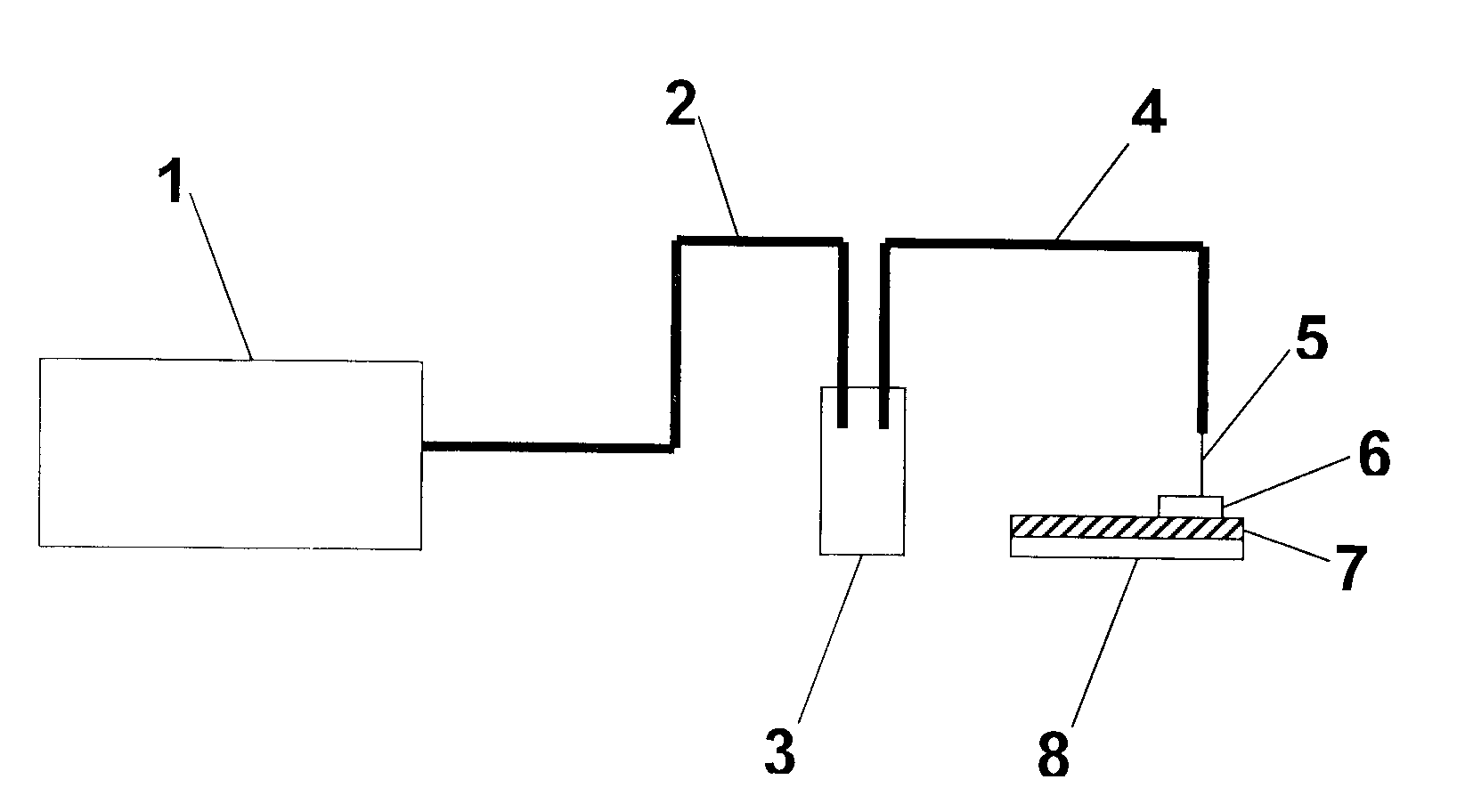
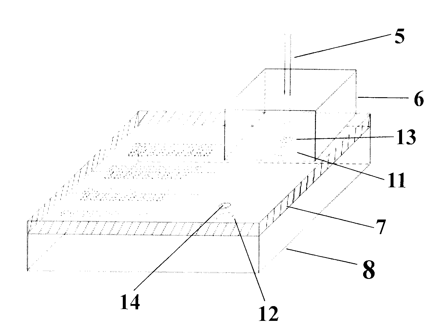
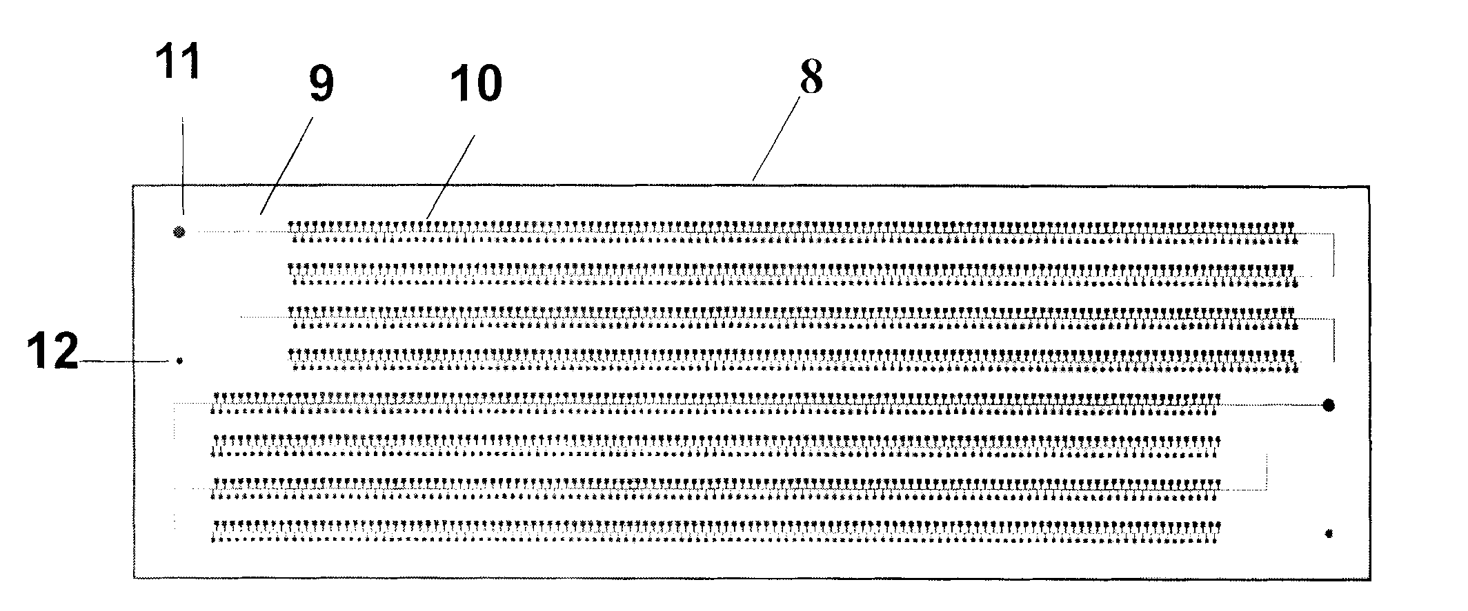
[0037] see figure 1 , figure 2 , image 3 , an integrated flow chip device for digital nucleic acid amplification, which consists of a vacuum system 1 (such as a vacuum pump), a front pipeline 2, a buffer bottle 3, a rear pipeline 4, a capillary 5, a suction cup 6, and a sealing layer 7 It is composed of the channel layer 8, and the channel layer 8 is sealed with the sealing layer 7 to form an integrated flow chip assembly. The suction cup 6 is placed on the integrated flow chip assembly. The channel layer 8 is engraved with channels, sample inlets 12 and sample outlets. Port 11, the channel is composed of a meandering main channel 9 and a number of side chambers 10 located on both sides of the main channel 9, the two ends of the main channel 9 are respectively connected to the sample port 11 and the sample inlet 12, and one end of the front pipeline 2 is connected to a vacuum In the system 1, the other end is connected to the buffer bottle 3, and one end of the rear pipeli...

Embodiment 2

[0045] see figure 1 , figure 2 , image 3 , with reference to Example 1, an integrated flow chip device for digital nucleic acid amplification, which consists of a vacuum system 1 (such as a vacuum pump), a front pipeline 2, a buffer bottle 3, a rear pipeline 4, a capillary 5, and a suction cup 6 , a sealing layer 7 and a channel layer 8, the channel layer 8 and the sealing layer 7 are sealed to form an integrated flow chip assembly, the suction cup 6 is placed on the integrated flow chip assembly, and the channel layer 8 is provided with channels and inlets The sample port 12 and the sample outlet port 11 are composed of a meandering main channel 9 and several side chambers 10 located on both sides of the main channel 9. The two ends of the main channel 9 are respectively connected to the sample port 11 and the sample inlet 12. One end of the front pipeline 2 is connected to the vacuum system 1, and the other end is connected to the buffer bottle 3. One end of the rear pip...

Embodiment 3

[0053] The structure of the integrated flow chip device for digital nucleic acid amplification in this embodiment can be found in figure 1 , figure 2 , image 3 , with reference to embodiment 1. It consists of a vacuum system 1 (such as a vacuum pump), a front pipeline 2, a buffer bottle 3, a rear pipeline 4, a capillary 5, a suction cup 6, a sealing layer 7 and a channel layer 8, and the channel layer 8 is sealed with the sealing layer 7 Finally, the integrated flow chip assembly is formed. The suction cup 6 is placed on the integrated flow chip assembly. The channel layer 8 is provided with a channel, a sample inlet 12 and a sample outlet 11. The channel consists of a meandering main channel 9 and a channel located in the main channel. 9 consists of a number of side chambers 10 on both sides, the two ends of the main channel 9 are respectively connected to the sample port 11 and the sample inlet 12; one end of the front pipeline 2 is connected to the vacuum system 1, the ...


PUM

PropertyMeasurementUnit
widthaaaaaaaaaa
depthaaaaaaaaaa
thicknessaaaaaaaaaa

Abstract

The invention provides an integrated fluidic chip device for digital nucleic acid amplification. The device consists of a vacuum system, a front pipeline, a buffer bottle, a rear pipeline, a capillary tube, a sucking disc, a sealing layer and a passage layer, wherein the passage layer and the sealing layer are sealed to form an integrated fluidic chip assembly; the passage layer is engraved with a passage and provided with a sample outlet and a sample inlet; the passage consists of a sinuous main passage and a plurality of side chambers positioned on two sides of the main passage; the two tail ends of the main passage are connected with the sample outlet and the sample inlet respectively; one end of the front pipeline is connected with the vacuum system, while the other end is connected with the buffer bottle; one end of the rear pipeline is connected with the buffer bottle, while the other end is connected with the capillary tube; and the capillary tube passes through the sucking disc and is communicated with the integrated fluidic chip assembly. The device has the advantages of reasonable design, microminiaturization, portability and simple operation, can distribute micro fluid into thousands of independent small chambers in dozens of seconds, reduce the complexity of chip manufacture and use and improve experiment speed, and can be applied in digital nucleic acid amplification.

Description

technical field [0001] The invention belongs to detection devices in various fields such as life sciences, medicine, chemistry and engineering, and relates to an integrated flow chip device for digital nucleic acid amplification and its application. Background technique [0002] It has been proved that many human diseases are directly or indirectly related to genes, and genes are DNA (deoxyribonucleic acid) molecular fragments with genetic effects. Therefore, the detection and analysis of nucleic acid is not only widely used in medical fields such as genetic diseases, tumors and infectious diseases, but also plays an increasingly important role in forensic identification, food safety, archaeology and other fields. However, although nucleic acid research has achieved remarkable results, it is also facing more challenges. First of all, the growth and development of organisms are not determined by a single gene, but the result of the synergy of multiple genes, which is a very ...

Claims


Application Information

Patent Timeline
Patent Type & Authority Applications(China)
IPC IPC(8): C12M1/00C12Q1/68
Inventor 黄江牟颖金钦汉金伟吴青青朱强远
Owner ZHEJIANG UNIV
Why Eureka
Try Eureka