Vacuum magnetron sputtering coating production line system of continuous solar energy collector chip

A technology of solar collector plate and coating production line, which is applied in sputtering coating, vacuum evaporation coating, ion implantation coating and other directions, can solve the secondary pollution of the film layer, affect the heat collection efficiency of the collector plate core, and destroy the film layer performance and other issues, to achieve the effect of improving weather resistance, strong market competitiveness and vitality, and improving production efficiency

Inactive Publication Date: 2011-03-16
魏海波 +1
View PDF1 Cites 26 Cited by
  • Summary
  • Abstract
  • Description
  • Claims
  • Application Information

AI Technical Summary

Problems solved by technology

This kind of heat-collecting film is mainly produced on the strip of copper substrate. When manufacturing the core of the flat collector plate, the strip needs to be cut. At the same time, the tubes are welded by ultrasonic welding on the back of each fin. On the one hand, the film will be destroyed during the welding process. On the other hand, the secondary pollution of the film layer will be caused during the whole plate core assembly and welding process, which will affect the heat collection efficiency of the heat collector plate core

Method used


Image

  • Vacuum magnetron sputtering coating production line system of continuous solar energy collector chip
  • Vacuum magnetron sputtering coating production line system of continuous solar energy collector chip
  • Vacuum magnetron sputtering coating production line system of continuous solar energy collector chip

Examples


example 1

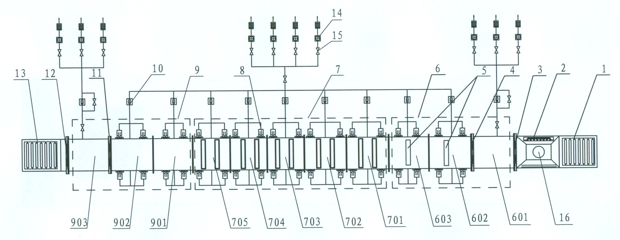
[0024] Such as figure 1 As shown, the main structure of the present invention includes a coating line system, which is a film-loading table 1, a dust-proof heating chamber 16 provided with a high-efficiency heater and a temperature control device 2, a film-in area 6, a film-coating area 7, a film-out area 9, a lower The film table 13, the evacuation system and the transmission mechanism running through the entire production line system, the film feeding area 6 includes a film feeding chamber 601, a film feeding transition chamber 602 and a film feeding buffer room 603, and the coating area 7 includes a deposition of high reflectivity metal layer coating Chamber 701, depositing different absorbing layer coating chambers 702 and 703 with different metal contents, depositing anti-reflection layer coating chamber 704 and depositing protective layer coating chamber 705, film output area 9 includes film output buffer chamber 901, film output transition chamber 902 and film output In...

example 2

[0030] Such as Figure 4 As shown, the main structure of the present invention includes a loading table 1, a dust-proof heating chamber 16 provided with a high-efficiency heater and a temperature control device 2, an entry and exit area 31, a coating area 32, an unloading table 13, an evacuation system and a through-hole The transmission mechanism of the production line system, the entry and exit area includes the entry and exit film chamber 3101, the entry and exit transition chamber 3102 and the entry and exit buffer chamber 3103, and the coating area includes the deposition protective layer coating chamber 3201, the deposition of high reflectivity metal layer and anti-reflection layer coating Chamber 3202 and absorption layer coating chamber 3203 with different deposited metal content; loading table 1, dustproof heating chamber 16, unloading table 13, film in and out chamber 3101, film in and out transition chamber 3102, film in and out buffer room 3103, depositing protectiv...


PUM


Abstract

The invention provides a vacuum magnetron sputtering coating production line system of a continuous solar energy collector chip. The system comprises an upper chip board, a dustproof heating chamber, a chip inlet area, a coating area, a chip outlet area, a lower chip board, evacuators and a transmission mechanism penetrating through the whole production line system. The technical key points of the system are characterized in that each part is connected in sequence; and the evacuators are arranged at the two sides of the production line system. In the system provided by the invention, a modular structure is used and a whole plate solar energy collector chip is horizontally conveyed, thus realizing the continuous coating production from an atmosphere state to vacuum coating and then from the vacuum coating to the atmosphere state. The production line system has the advantages that an ideal spectral selection coating can be prepared on a large-area whole plate solar energy chip; and the coating is even, and is good in physicochemical performance and long in service life. By means of the production line system provided by the invention, mass industrial production of the selective absorption coatings of the solar energy collector chips can be realized, thus the production efficiency is improved, the cost is reduced, and pollution is not generated during the production process.

Description

technical field [0001] The invention belongs to the technical field of solar heat collecting plates and vacuum coatings, in particular to a continuous solar heat collecting plate chip vacuum magnetron sputtering coating production line system, which deposits solar energy absorbing coatings on the entire heat collecting chip substrate. layer. Background technique [0002] With the promotion and popularization of new energy sources, as well as the progress and development of science and technology, the integration of solar energy and buildings has higher and higher technical requirements for solar water heaters, and the market demand is becoming more and more urgent. In urban buildings, the bottleneck problems encountered by vacuum tube products in terms of installation height, public safety, pipeline, quality and city appearance construction have become increasingly prominent. The flat plate collector has its own advantages such as pressure resistance, double circulation sy...

Claims


Application Information

Patent Timeline
Patent Type & Authority Applications(China)
IPC IPC(8): C23C14/34C23C14/56
Inventor 魏海波龚肖南
Owner 魏海波
Why Eureka
Try Eureka