Method for magnetically processing fuel

A processing method and fuel magnetization technology, which are applied in combustion air/combustion-air processing, charging system, combustion engine, etc., can solve the problems of energy consumption and carbon dioxide emission, and achieve the effect of improving combustion rate and preventing air pollution.

Active Publication Date: 2011-03-23
微垦智能科技(上海)有限公司
View PDF4 Cites 13 Cited by
  • Summary
  • Abstract
  • Description
  • Claims
  • Application Information

AI Technical Summary

Problems solved by technology

[0026] 2. Incomplete combustion of fuel will also produce toxic carbon monoxide (CO) and hydrocarbons (HC)
At the same time, "incomplete combustion of fuel" will inevitably cause a large amount of unnecessary energy consumption and carbon dioxide (CO2) emissions

Method used


Image

  • Method for magnetically processing fuel
  • Method for magnetically processing fuel
  • Method for magnetically processing fuel

Examples


Embodiment 1

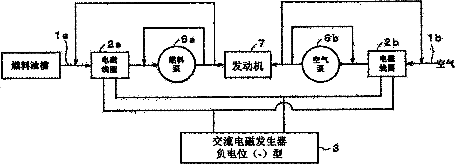
[0121] Example 1: Table 1 is in figure 1 In the system, the coil 2a is installed on the fuel supply line 1a of the engine 7; the ceramic radiation type electromagnetic coil module is installed on the air supply line 1b, and the electromagnetic generator in Figure 3 or Figure 4 is used to direct the coil 2a and the ceramic radiation type The electromagnetic coil module 2b outputs the following AC currents: (a) AC current with a single main frequency; the present invention can use one or more output waveform signals with a peak frequency range of 4000Hz to 25000Hz as needed; (b) ) Several kinds of mixed AC currents with different single frequencies; the present invention can use one or more output waveform signals with a peak frequency range of 4000Hz to 25000Hz as required; (c) Have the signal at 4000-25000Hz as shown in Figure 6 An alternating current whose frequency changes with time; the fuel and air are magnetized by the alternating magnetic field generated by the electromagn...

Embodiment 2

[0126] Example 2: Take figure 1 The shown system installs an electromagnetic coil 2a on the fuel supply pipe 1a of the engine 7 and an electromagnetic coil 2b on the combustion air supply pipe 1b. The electromagnetic coil 2b here is an electromagnetic coil module with a ceramic layer. The generator (negative potential type) supplies alternating currents of different intensities to the electromagnetic coil 2a and the electromagnetic coil 2b to test the magnetization effect of the output power of the present invention on the fuel. Among them, when the electromagnetic coil is not supplied with current, it can be regarded as "untreated" without magnetization for comparison. The calculation method of output power is W (watt) = the product of I (current) and V (voltage). The frequency of the AC current used in the test is the AC current within 4KHz-25KHz: (1) AC current with a single frequency; (2) Several mixed AC currents with different single frequencies; (3) Frequency with time ...

Embodiment 3

[0158] Example 3: Picture 10 for figure 1 A schematic cross-sectional view of an air cleaner 10 that provides combustion air to the engine 7 in the system shown. A filter element 11 is installed in the air cleaner, and a stainless steel metal mesh 12 with honeycomb-shaped openings and silver-plated surface is installed on the upper or lower part of the filter element. The metal mesh 12 is referred to in Table-9 and Table-10 for short. Metal mesh-silver'. Another type of mesh structure module is to arrange ceramic balls ('IonTechno Ball' manufactured by Furuya Institute of Technology Co., Ltd., Japan) with a diameter of approximately 5 mm on a stainless steel metal mesh in a go-board-like array. The arrangement density is approximately One particle in the range of 10mmX10mm. The metal mesh 12 equipped with ceramic balls is listed in Table 9, and is referred to as "metal mesh-ceramic" in Table 10. The negatively charged electromagnetic generator of Figure 3 is used in the test p...


PUM


Abstract

The invention discloses a method for magnetically processing fuel. The method comprises the following steps of: installing an electromagnetic coil on a supply system which supplies fuel to an engine combustion device, and connecting two joints of the electromagnetic coil with an electromagnetic generating device; and providing an alternating current to the electromagnetic coil through the electromagnetic generating device so that the electromagnetic coil generates an alternating current magnetic field, and magnetizing the fuel in an engine by utilizing the alternating current magnetic field, wherein the frequency domain of the alternating current is 4-25kHz. The invention can improve the combustion efficiency of various fuels, enhance the power output performance of the engine, inhibit the emission of various pollution gases generated by harmful substances in the fuel due to oxidization and prolong the life of engine lubricating oil.

Description

technical field [0001] The invention relates to a fuel treatment method, in particular to a fuel magnetization treatment method. Background technique [0002] The working principles of various engines in the world at present, taking the four-stroke engine as an example: [0003] 1. Suction stroke: the piston descends → inhales the atomized fuel and fresh air (oxygen) from the outside into the cylinder → forms a mixed gas of oil and gas; [0004] 2. Compression stroke: the piston rises → compresses the oil-gas mixture → increases the temperature of the mixture through compression; [0005] 3. Power stroke: through ignition, the compressed oil-gas mixture is explosively burned; the gas volume in the cylinder expands sharply, pushing the piston downward; the energy of this downward movement is used to output to drive each cylinder A kind of equipment (automobile, ship, etc.), in which the gasoline engine is ignited by the spark plug discharge, and the diesel engine is ignited...

Claims


Application Information

Patent Timeline
Patent Type & Authority Applications(China)
IPC IPC(8): F02M27/04
CPCF02M27/04Y02T10/126F02M2027/047F02M27/02C10G32/02
Inventor 深町进平长谷川学
Owner 微垦智能科技(上海)有限公司
Why Eureka
Try Eureka