Method and equipment for using waste gas of butadiene extraction unit

An extraction device and butadiene technology, applied in chemical instruments and methods, gas mixture processing, hydrocarbon oil treatment, etc., can solve the problems of diene and alkyne polymerization, catalyst deactivation, etc., and reach the content of alkyne The effect of reducing and maintaining catalytic performance and improving the utilization rate of C4

Active Publication Date: 2011-03-30
CHINA PETROLEUM & CHEM CORP +1
View PDF3 Cites 13 Cited by
  • Summary
  • Abstract
  • Description
  • Claims
  • Application Information

AI Technical Summary

Problems solved by technology

[0009] In order to solve the feed problem of the reactor, the catalyst is easily deactivated due to the high content of alkyne and diene in the raw material and the po

Method used


Image

  • Method and equipment for using waste gas of butadiene extraction unit
  • Method and equipment for using waste gas of butadiene extraction unit
  • Method and equipment for using waste gas of butadiene extraction unit

Examples


Embodiment 1

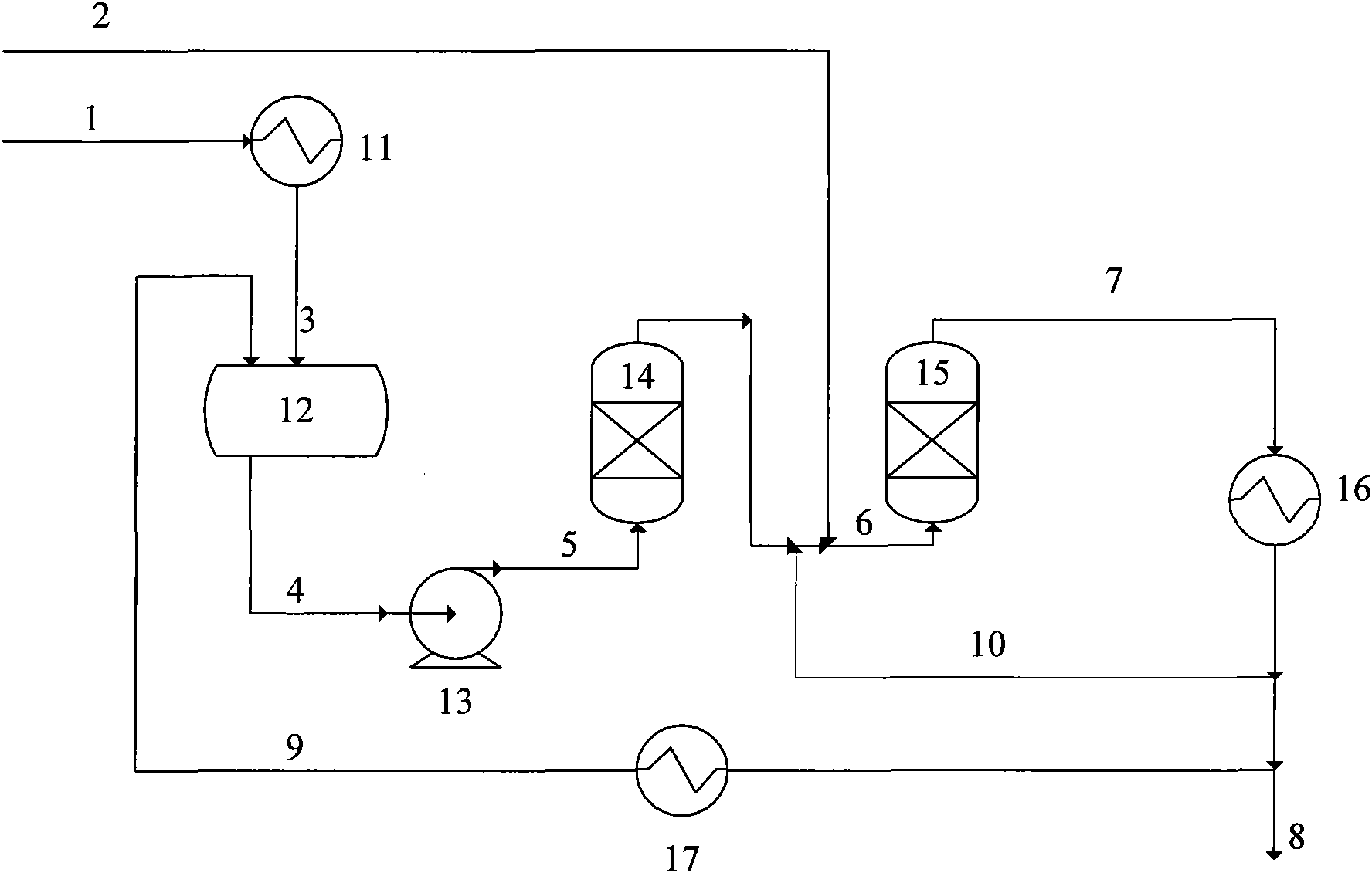
[0043] 1. Condensation: tail gas 1 from the butadiene extraction unit (main composition: butene 0.5%, butadiene 56.3%, ethyl acetylene and vinyl acetylene 40.8%, carbon five 2.4%), flow rate 1200kg / h, Pressure 0.1MPa (absolute pressure). The tail gas is condensed into a liquid phase material 3 through the condenser, the temperature is -5°C, the liquid phase mixture enters the mixing tank 12, and is mixed with the dilute alkane 9 from the reactor product, the flow rate of the dilute alkane 9 is 1200kg / h, and the temperature is -3 °C, pressure 0.1MPa, the content of ethylacetylene and vinylacetylene in the mixed material 4 is 20%;

[0044] 2. Boosting: the diluted mixture flow 4 is boosted to 2.0-2.5MPa by the pump, and a booster pump with high speed and high head can be selected;

[0045] 3. Drying: the pressurized mixture 5 enters the drier 14 for drying to remove trace moisture therein;

[0046] 4. Reaction: The dried mixture is mixed with the circulating alkane 10, the flo...

Embodiment 2

[0051] Adopt flow process described in embodiment 1, change the composition of stream 1, the quality composition of each main stream of hydrogenation reaction is as follows table 2:

[0052] Table 2

[0053]

Embodiment 3

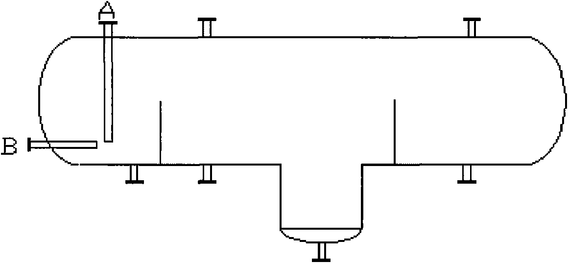
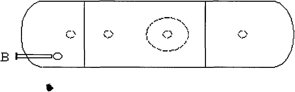
[0055] combined with figure 2 and image 3 As shown, the structure of the mixing tank used in Examples 1 and 2 is as follows: tail gas condensate 3 is fed from the top of the mixing tank by gravity, and the feed port is 1 / 3 of the tank diameter from the bottom of the mixing tank; Feeding along the horizontal direction, the distance between the feed inlet and the feed inlet of the condensate 3 is 3 times the diameter of the raw material pipe; the vortex baffle is set up at the inlet of the booster pump at 1 / 3 of the length of the mixing tank, and the height of the baffle is dia. 2 / 3 of that; the alkane used for dilution enters the mixing tank and forms a vortex in the tank, which can be fully mixed with the liquid phase raw materials.


PUM


Abstract

The invention relates to a method for using waste gas of a butadiene extraction unit, comprising the following steps: (1) condensation and pressurization: introducing waste gas materials from the extraction unit to a condenser, condensing the materials to liquid phases to enter a mixing tank, completely mixing the liquid phases with diluted alkane from hydrogenated products of step (2) in the mixed tank, then entering to a pump, pressurizing by the pump; and (2) hydrogenation: mixing the mixed material flow pressurized in step (1) with cycling alkane from hydrogenated products, adding hydrogen in a certain ratio and then entering a hydrogenation reactor, cooling the hydrogenated products at the outlet of the reactor to normal temperature, and dividing the cooled products into three parts,wherein one part is taken as diluted alkane to enter the mixed tank in step (1), one part is taken as cycling alkane to enter inlet of the reactor, and the rest part is served as alkane products. Thehydrogenated products in the invention can be taken as the fuels, can be returned to a cracking furnace as cracking stocks to replace parts of naphtha, and also can be taken as high-purity alkane which is sent to a downstream unit for being a raw material, thereby reaching the purposes of saving resources and improving the rate of multipurpose utilization of C4.

Description

technical field [0001] The invention relates to the field of recovery and utilization of petrochemical waste gas, in particular to a method and equipment for utilization of alkyne-rich waste gas from a butadiene extraction device. Background technique [0002] When the ethylene cracking unit co-produces C4 hydrocarbons, the 1,3-butadiene in the cracked C4 hydrocarbons is usually refined by two-stage solvent extraction rectification and then direct rectification. The residual waste gas produced by this refining device is commonly known as butadiene exhaust. Extractive distillation is also called extraction, and the recovery device of butadiene is generally called butadiene extraction device. The alkyne concentration in the butadiene tail gas is relatively high, generally greater than 20% by weight, and the highest can exceed 40% by weight. These alkyne-rich waste gases have no industrial value at present and can only be sent to torch for combustion. Because high-concentrat...

Claims


Application Information

Patent Timeline
IPC IPC(8): C07C9/10C07C5/03C07C5/08C10G70/02B01J23/755B01J23/75B01J23/72B01J23/52B01J23/50B01J23/44B01J23/34
Inventor 李东风张勇程建民乐毅徐立英廖丽华过良刘智信王婧
Owner CHINA PETROLEUM & CHEM CORP
Why Eureka
Try Eureka