Method for flexibly adjusting catalytic cracking reaction-regeneration system heat balance

A regenerative system and heat balance technology, applied in catalytic cracking, cracking, petroleum industry, etc., can solve the problems of fixed heat load, impact, and average density reduction

Active Publication Date: 2013-03-06
CHINA UNIV OF PETROLEUM (BEIJING)
View PDF8 Cites 0 Cited by
  • Summary
  • Abstract
  • Description
  • Claims
  • Application Information

AI Technical Summary

Problems solved by technology

However, to achieve an appropriate reaction temperature under high catalyst circulation in the riser reactor and to maintain a relatively high regenerator catalyst bed temperature to ensure the regeneration effect of the catalyst, only relying on the use of a separate regenerated catalyst described in the above-mentioned patent to take It is difficult to achieve two-way regulation of thermal equipment, because increasing the catalyst circulation in the riser reactor requires a substantial increase in the heat extraction load of the regenerator heat extractor, which will inevitably interfere with the catalyst bed temperature of the regenerator
[0006] Chinese patent CN99120517 discloses a cooling method for heavy oil catalytic cracking regenerated catalyst. This method only relies on the regenerated catalyst cooler installed on the regenerated agent delivery pipeline to reduce the temperature of the regenerated catalyst to increase the catalyst circulation in the riser reactor of the catalytic cracking unit. However, this method does not consider adjusting the catalyst material level in the heat receiver to achieve flexible adjustment of the heat extraction load, so there are disadvantages of relatively fixed heat extraction load and poor adjustment flexibility.
However, relying on the temperature adjustment equipment described in the above-mentioned patents to achieve a two-way increase in heat load and agent-oil ratio is difficult to implement in engineering
For example, when it is required to increase the heat extraction load, it must be achieved by increasing the fluidization air volume to expand the catalyst bed in the temperature control equipment (increase the heat transfer area) and increase the degree of catalyst turbulence (increase the heat transfer coefficient). However, the catalyst bed After layer expansion, the average density of the catalyst bed is greatly reduced, which will reduce the driving force of the catalyst entering the riser reactor, and at the same time increase the amount of gas carried by the catalyst entering the riser reactor, which directly affects the reaction process. Ratio of improvement
At the same time, these patents propose that the temperature adjustment range of the regenerated catalyst is 630-660°C, but this temperature range is not feasible for any device, especially when the coke yield of the device is low, the regenerated catalyst is cooled to 630-660°C Too much heat is required, causing the regeneration temperature to be too low, which affects catalyst burnt regeneration
Moreover, the temperature range of 630-660°C is obviously low for raw materials with large carbon residues processed by catalytic cracking units, which will make it difficult to gasify high-boiling components; while for raw materials with carbon residues less than 4.0wt%, the temperature range of 630-660°C The range is obviously too high, which will cause poor thermal cracking reaction inhibition effect
[0008] Chinese patent CN2005100585695.4 discloses a heavy oil catalytic conversion method and its device. The method proposes that two riser reaction systems, or one riser reactor, be divided into two reaction zones for two cooling catalysts to participate in the reaction, improving This method does not explain how to realize the distribution and adjustment of the heat load between the regenerator and the reactor when cooling the two streams of catalysts separately. At the same time, this method is not aimed at the current conventional catalytic cracking riser reaction system. Personnel cannot use this teaching to push their inventions to conventional conventional riser reaction systems
[0009] Based on the above, it can be seen that when the previous patents emphasized the invention of heat extraction and cooling of the regenerated catalyst before entering the riser reactor, it did not involve the operation of the regenerator and the maintenance of the heat balance of the device, especially the adjustment and maintenance of the conventional heat extractor. match operation

Method used


Image

  • Method for flexibly adjusting catalytic cracking reaction-regeneration system heat balance
  • Method for flexibly adjusting catalytic cracking reaction-regeneration system heat balance
  • Method for flexibly adjusting catalytic cracking reaction-regeneration system heat balance

Examples


specific Embodiment approach 2

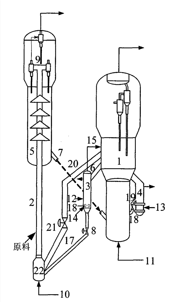
[0023] The process of the present invention can also be seen figure 2 , briefly described as follows: a conventional catalyst heat taker 4 is set on the regenerator 1 of the heavy oil catalytic cracking unit, and a part of the high-temperature catalyst in the regenerator 1 (accounting for 1% to 20% of the regenerator catalyst reserve) enters the conventional catalyst to take heat The heat exchanger 4 exchanges heat with the cooling medium 13 (water or low-pressure steam) and returns to the regenerator through the catalyst delivery pipe 18 and the catalyst flow control valve 19. The opening degree is adjusted, and the heat extraction is adjusted by the circulation amount of the catalyst entering the heat extractor and the flow rate of the cooling medium 13 (water or low-pressure steam). The low temperature catalyst (550~660℃) returned to the regenerator is mixed with the high temperature catalyst in the regenerator, so as to realize the adjustment of the catalyst bed temperatu...

specific Embodiment approach 3

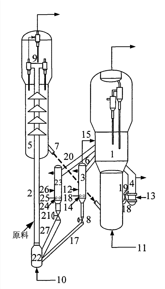
[0027] The process of the present invention can also be seen image 3 , briefly described as follows: a conventional catalyst heat taker 4 is set on the regenerator 1 of the heavy oil catalytic cracking unit, and a part of the high-temperature catalyst in the regenerator 1 (accounting for 1% to 20% of the regenerator catalyst reserve) enters the conventional catalyst to take heat The heat exchanger 4 exchanges heat with the cooling medium 13 (water or low-pressure steam) and returns to the regenerator through the catalyst delivery pipe 18 and the catalyst flow control valve 19. The opening degree is adjusted, and the heat extraction is adjusted by the circulation amount of the catalyst entering the heat extractor and the flow rate of the cooling medium 13 (water or low-pressure steam). The low temperature catalyst (550~660℃) returned to the regenerator is mixed with the high temperature catalyst in the regenerator, so as to realize the adjustment of the catalyst bed temperatur...

Embodiment 1

[0037] For verifying the effect of the present invention, adopt figure 2 The technological process shown is carried out industrial test on a 400,000 ton / year heavy oil catalytic cracking unit of a refinery, and the test results are listed in Table 1.

[0038] After adopting this invention, under the condition that the catalyst bed temperature of the regenerator is kept at 690°C, the regenerated catalyst entering the riser reactor is cooled to 660°C, the oil agent mixing temperature is 560°C, and the agent-oil ratio is increased from 6 to 9, The reaction temperature was maintained at 490°C, so that the yield of light oil increased by 2.3 percentage points, and the yield of dry gas and coke decreased significantly. See Table 1 for details.

[0039] Table 1 Properties of heavy oil raw materials

[0040] project

data

project

data

Density(20℃)kg / m 3

945

Nitrogen content, ppm

2000

Carbon residue, wt%

5.4

Hydrocarb...


PUM


Abstract

The invention relates to a method for flexibly adjusting catalytic cracking reaction-regeneration system heat balance. A conventional regenerated catalyst heat remover which is arranged beside a regenerator and a regenerated catalyst cooler which is arranged on a regenerated catalyst conveying pipe are coupled and linked so that the catalyst bed temperature in the regenerator is controlled in one aspect to solve the problem of catalyst inactivation because of overhigh temperature caused by great scorching amount in a traditional heavy oil catalytic cracking device and too much heat in the regenerator, and the carried heat and the temperature of the regenerated catalyst entering a lifting pipe reactor are adjusted in the other aspect to adjust ratios of different catalyst and oil needed for raw materials with different properties in cracking reactions. The invention takes heat and adjusts the temperatures of high-temperature regenerated catalysts in different positions in a traditional heavy oil catalytic cracking device and flexibly adjusts the reaction-regeneration system heat balance so as to optimize heavy oil catalytic cracking process conditions and remarkably improve the yield of light oil and liquid.

Description

technical field [0001] The invention relates to a method for adjusting the heat balance of a reaction-regeneration system of a heavy oil catalytic cracking unit, belonging to the technical field of petroleum processing. Background technique [0002] In the catalytic cracking unit, the coking regeneration process of the catalyst releases a lot of heat. Due to the circulating flow of the catalyst between the regenerator and the reactor, the heat energy at the high temperature is carried into the riser reactor to meet the needs of the lower temperature cracking reaction. , so as to keep the regeneration and cracking processes to reach the required temperature and realize the heat balance of the reaction-regeneration system of the heavy oil catalytic cracking unit. However, in recent years, the heaviness of FCC feedstock has become increasingly serious, and its density, carbon residue, colloid, and asphaltene content have gradually increased. As a result, the coke yield during t...

Claims


Application Information

Patent Timeline
Patent Type & Authority Patents(China)
IPC IPC(8): C10G11/00
Inventor 王刚高金森徐春明蓝兴英文尧顺卢春喜
Owner CHINA UNIV OF PETROLEUM (BEIJING)
Why Eureka
Try Eureka