

Optical fiber eat treatment method and device
A technology of heat treatment device and heat treatment method, applied in glass manufacturing equipment, glass production, manufacturing tools, etc., can solve the problem of unspecified holding time and holding furnace temperature setting, unspecified length of temperature zone, optical fiber processing time, complicated application, etc. problem, to achieve the effect of reducing Rayleigh backscattering loss, reducing small density changes, and reducing attenuation coefficient
- Summary
- Abstract
- Description
- Claims
- Application Information
AI Technical Summary
Problems solved by technology
Method used
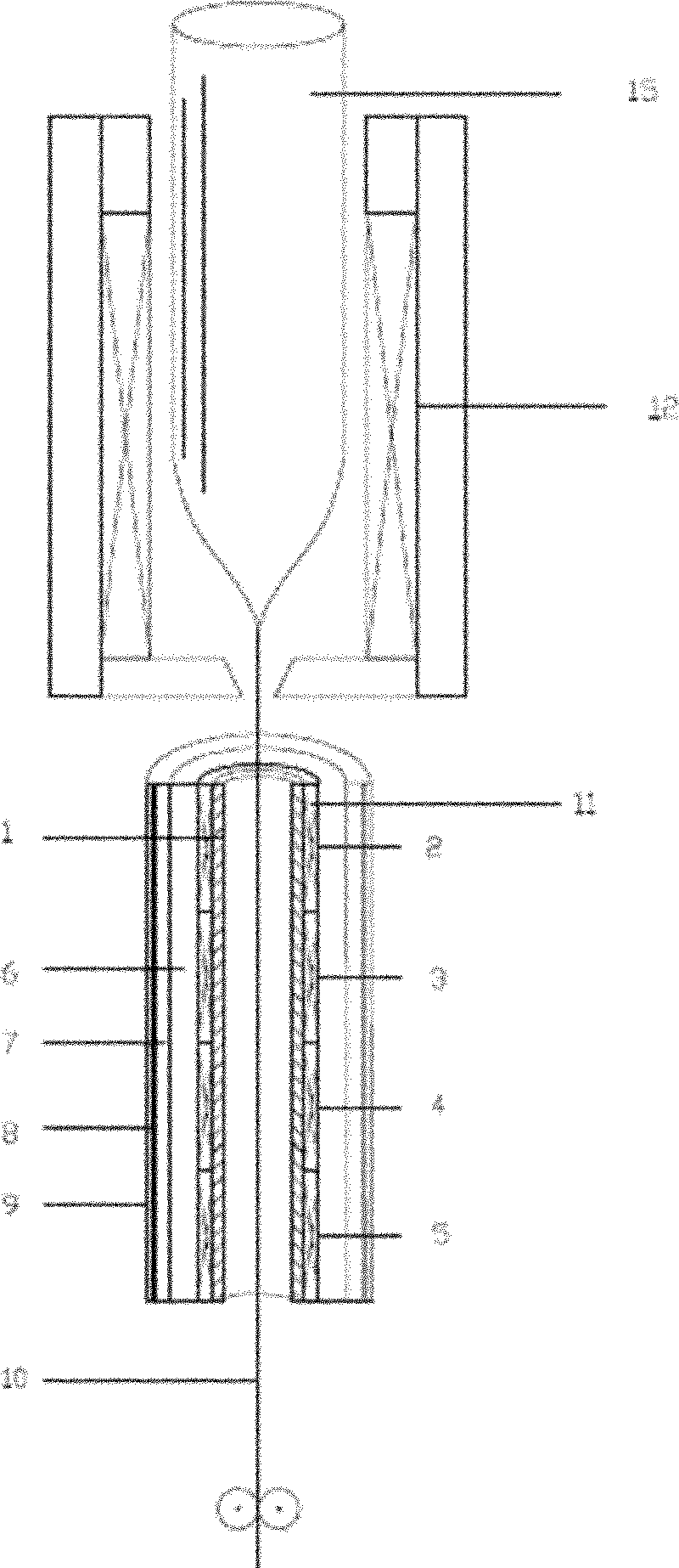
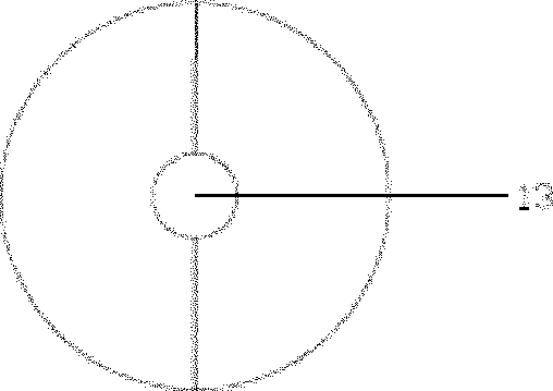
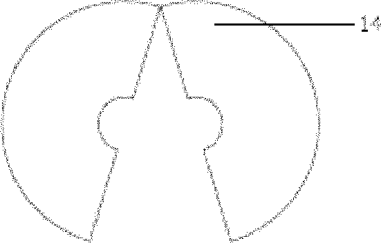
Image

Examples
Embodiment 1
[0026] The fiber corresponding to Example 1 is a core rod prepared by the PCVD method, and a germanium-fluorine-doped matched-clad single-mode fiber with the cladding prepared by the OVD method. The length and temperature parameters of the holding furnace are chosen such that the temperature of the fiber is maintained at the desired temperature for a period of time. Specifically, the furnace chamber of the holding furnace is divided into two temperature-controlled areas, each with a length of 1 m; the temperatures in the first area and the second area are 850°C and 1050°C, respectively. The drawing speed is set at 1300m / min, the total residence time of the optical fiber in the holding furnace is about 0.09s, and the residence time in each temperature-controlled area is about 0.045s. The surface temperature of the optical fiber entering the holding furnace is 1476°C, and the surface temperature of the optical fiber leaving the holding furnace is 1156°C. The average cooling rat...
Embodiment 2
[0029]The optical fiber corresponding to Example 2 is a core rod prepared by PCVD method, and a germanium-fluorine-doped matched-clad single-mode optical fiber whose cladding is prepared by OVD method. The drawing speed is set at 1500m / min, and the temperature at which the optical fiber enters the holding furnace is 1511°C. The length and temperature parameters of the holding furnace are chosen such that the temperature of the fiber is maintained at the desired temperature for a period of time. Specifically, the heat zone of the holding furnace is divided into 3 zones, and the length of each zone is 1m; the temperatures in the first zone to the third zone are 800°C, 950°C, and 1050°C, respectively. In this way, the total residence time of the optical fiber in the holding furnace is about 0.12s, and the residence time in each hot zone is about 0.04s. The surface temperature of the optical fiber when it leaves the holding furnace is 1163°C. The average cooling rate in the hold...
Embodiment 3
[0033] The optical fiber corresponding to Example 3 is a core rod prepared by PCVD, and a germanium-fluorine-doped matched-clad single-mode optical fiber whose cladding is prepared by OVD. The drawing speed is set at 1800m / min, and the temperature at which the optical fiber enters the holding furnace is 1564°C. The length and temperature parameters of the holding furnace are chosen such that the temperature of the fiber is maintained at the desired temperature for a period of time. Specifically, the heat zone of the holding furnace is divided into 3 zones, and the length of each zone is 1m; the temperatures in the first zone to the third zone are 750°C, 950°C, and 1050°C, respectively. In this way, the total residence time of the optical fiber in the holding furnace is about 0.1s, and the residence time in each hot zone is about 0.033s. The surface temperature of the optical fiber when it leaves the holding furnace is 1158°C. The average cooling rate in the holding furnace i...
PUM
| Property | Measurement | Unit |
|---|---|---|
| thickness | aaaaa | aaaaa |
| thickness | aaaaa | aaaaa |
Abstract
Description
Claims
Application Information