Composite implant having porous structure filled with biodegradable alloy and method of magnesium-based manufacturing the same

A porous structure, magnesium-based alloy technology, applied in the direction of bone implants, dental implants, medical science, etc., can solve the problems of indistinguishable mechanical properties, poor impact resistance, difficult to control the biodegradability rate, etc., to avoid stress The effect of occlusion, accelerated bone formation, and improved bone formation rate

Inactive Publication Date: 2011-04-13
U & I INC
View PDF3 Cites 18 Cited by
  • Summary
  • Abstract
  • Description
  • Claims
  • Application Information

AI Technical Summary

Problems solved by technology

However, the mechanical properties of these materials cannot be significantly differentiated from those of biodegradable polymers
Especially, when ceramic materials are used as biomaterials, they have a fatal disadvantage because of their poor impact resistance
Furthermore, there is some doubt as to whether such materials will prove to be practically effective due to the difficulty in controlling their biodegradability rates.

Method used


Image

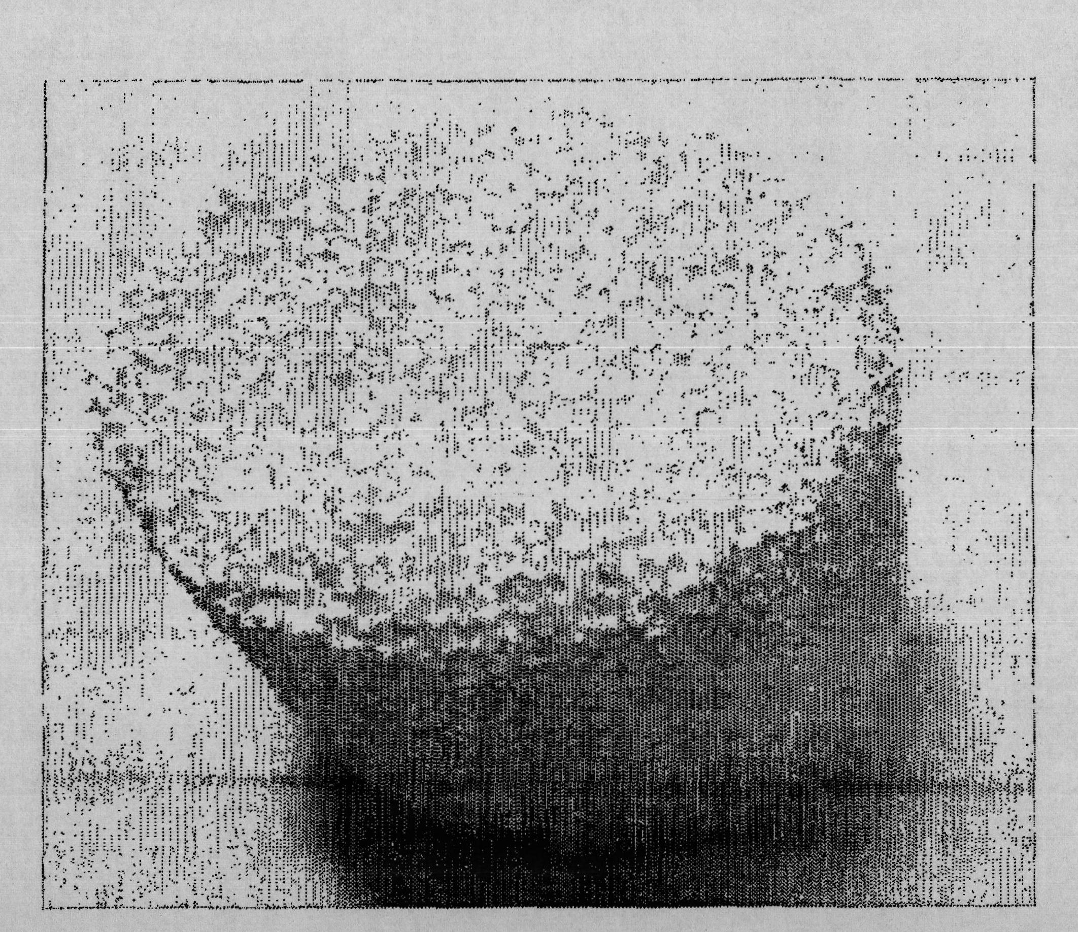
  • Composite implant having porous structure filled with biodegradable alloy and method of magnesium-based manufacturing the same
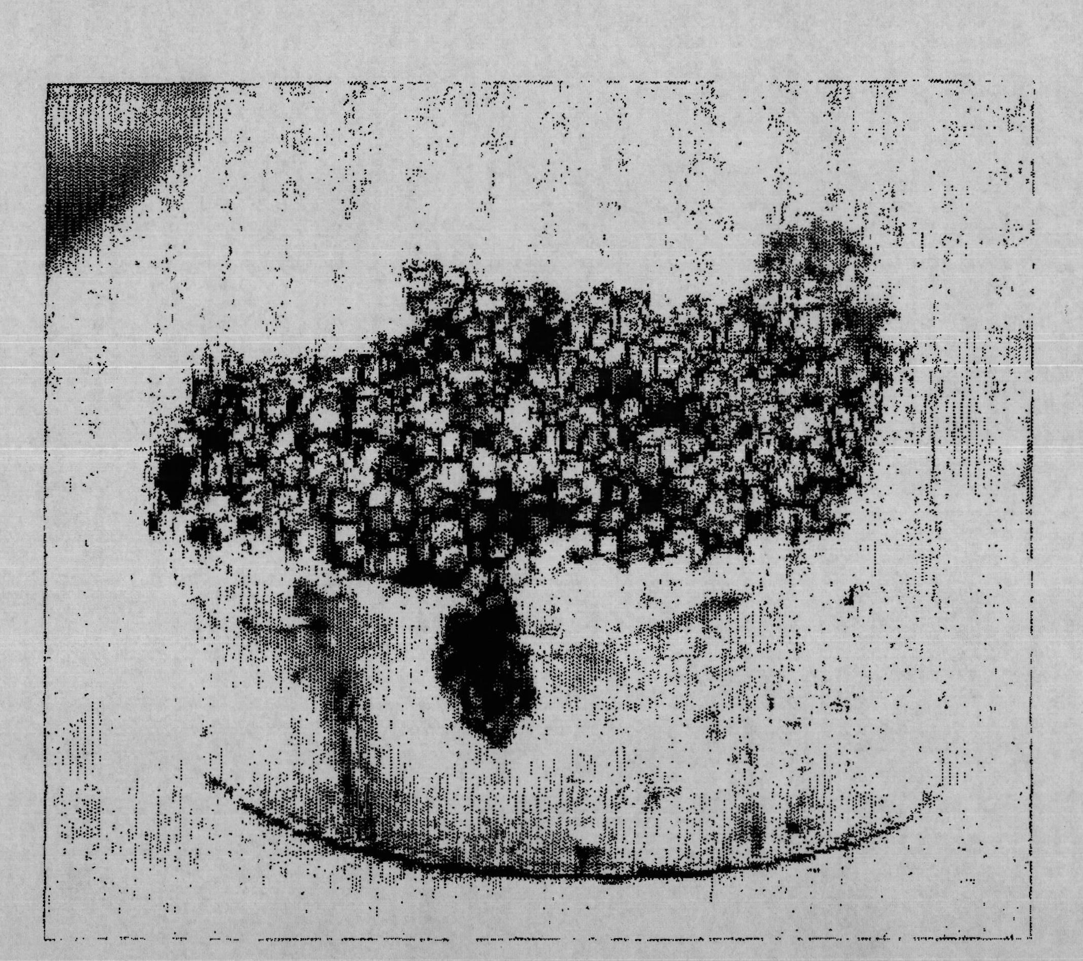
  • Composite implant having porous structure filled with biodegradable alloy and method of magnesium-based manufacturing the same
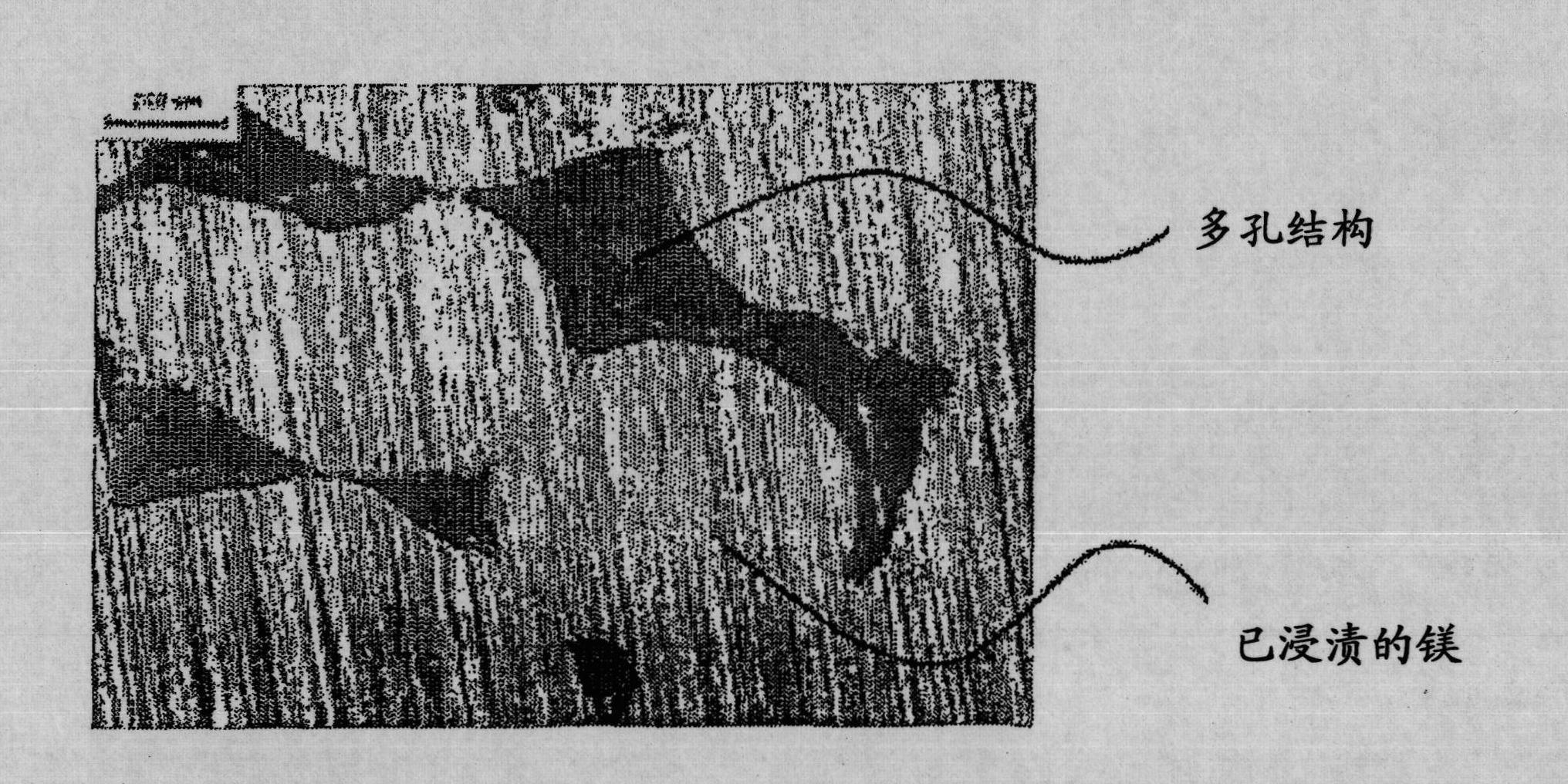
  • Composite implant having porous structure filled with biodegradable alloy and method of magnesium-based manufacturing the same

Examples


Embodiment 1

[0074] Example 1: Fabrication of Magnesium-Filled Alumina Implants

[0075] 200mL of alcohol, 6g of polyvinyl butyral (polyvinyl butyral-co-vinylalcohol-co-vinyl acetate, PVB), 6mL of trialkylphosphate (triethylphosphate, 99.8%), 50g of alumina were mixed and stirred for 2 hours to form The mixed solution is used as solvent, binder, dispersant and biodegradable ceramics respectively. Subsequently, spherical zirconia was added to the mixed solution and ball-milling was performed for about 24 hours. Next, immerse polyurethane (polyurethane) cut into a predetermined size and shape into the mixed solution, take it out, and then turn it at room temperature to avoid blocking the holes. Subsequently, the polyurethane was dried in the air for about 5 minutes, so that the high-concentration zirconia covered the polyurethane foam. As described above, the procedure of immersing the polyurethane into the mixed liquid and then drying the polyurethane may be performed repeatedly, thereb...

Embodiment 2

[0078] Example 2: Manufacture of Magnesium-Filled Titanium Implants

[0079] The titanium porous structure is prepared by the rotating electrode method. The spherical titanium powder with a diameter of 100-200 μm is placed between the conductive electrodes, and then a 450 μF capacitor is used under the condition of 1.0kj or 1.5kj by using a high vacuum switch. The voltage is immediately discharged, and the current and voltage flowing through the powder during the discharge are controlled, thus performing rapid sintering of the spherical titanium powder.

[0080] A copper electrode rod was provided in a quartz tube with an inner diameter of 4.0 mm, and 0.7 g of classified titanium powder was added into the quartz tube, followed by fully packing the titanium powder using a vibrator. At the same time, use an automatic charging device to apply a load of 10g to the upper part of the copper electrode rod, so that the copper electrode is in contact with the upper part of the titani...


PUM

PropertyMeasurementUnit
diameteraaaaaaaaaa
porosityaaaaaaaaaa

Abstract

The present invention provides a composite implant comprising pores of a porous structure filled with a biodegradable magnesium-based alloy. Further, the present invention provides a composite implant which filles pores of the porous structure prepared by a metal, a ceramic or a polymer with a biodegradable magnesium-based alloy. Mechanical properties of the composite implant of the present invention are improved because a magnesium-based alloy filled in its pores increases the strength of a porous structure comprised of a metal, a ceramic or a polymer. Futher, it can be expected that the magnesium-based alloy filled in the porous structure is decomposed in a living body, thus increasing bone formation rate. Accordingly bone tissue can be rapidly formed because the composite implant of the present invention has high strength and excellent interfacial force between the composite implant and bone tissue, compared to conventional porous materials.

Description

technical field [0001] The present invention relates to a composite implant having a porous structure filled with biodegradable alloy and a method for manufacturing the composite implant. More particularly, the present invention relates to a composite implant having a porous structure filled with biodegradable magnesium (magnesium) or magnesium-based alloy (magnesium-based alloy), thus having a Controllable biodegradation rate, which has high strength and excellent interfacial force between magnesium or magnesium-based alloy and bone tissue, and is also related to a method of manufacturing said composite implant . Background technique [0002] Typical materials for medical therapeutic implants include metals, ceramics, polymers, and the like. Among them, metal implants have excellent mechanical properties and workability, but there are still problems such as stress shielding, image degradation, implant displacement, etc. migration) and so on. Furthermore, although cerami...

Claims


Application Information

Patent Timeline
Patent Type & Authority Applications(China)
IPC IPC(8): A61F2/28
CPCA61L27/58A61L27/446A61L27/427A61F2/28A61C8/00
Inventor 石铉光梁硕祚金有灿具滋教
Owner U & I INC
Why Eureka
Try Eureka