Method for enhancing oil well cement slurry

A technology of oil well cement slurry and oil encounter, which is applied in the direction of chemical instruments and methods, drilling compositions, etc., can solve the problems of many uncertain factors, many influencing factors, wellbore temperature and pressure changes, etc., and is beneficial to on-site implementation. The method Simple, Wide-Source Effects

Active Publication Date: 2011-04-27
中国石油集团西部钻探工程有限公司克拉玛依钻井工艺研究院
View PDF3 Cites 11 Cited by
  • Summary
  • Abstract
  • Description
  • Claims
  • Application Information

AI Technical Summary

Problems solved by technology

[0003] However, well cementing is an underground system engineering with strong concealment, many uncertain factors, and many influencing factors. It is becoming more and more difficult to obtain sufficient guarantees, coupled with the serious impact of large-scale application of enhanced recovery measures on cementing quality, and the temperature and pressure in the wellbore during the production process have undergone greater or even significant changes compared with those during cementing, thus The channeling channel is formed, leading to annular channeling, which seriously affects the normal production and safe production of oil and gas fields
[0004] How to solve the problem of annulus channeling due to poor initial cementing quality, impact of subsequent operations and temperature and pressure changes in the wellbore, resulting in micro-cracks in the cement stone and micro-annular gaps on the cementing interface , to ensure the normal and safe production of oil and gas wells, has become an urgent cementing technical problem to be solved in major oil fields at home and abroad

Method used


Image

  • Method for enhancing oil well cement slurry
  • Method for enhancing oil well cement slurry
  • Method for enhancing oil well cement slurry

Examples


Embodiment 1

[0021] The cement slurry system used in the experiment is as follows:

[0022] 800g Xinjiang G grade oil well cement + 1.5% ST300C + 7% ST300L + 0.4% SXY-2 + 45% water

[0023] The specific additives in the formula are: ST300C is a crosslinking agent, ST300L is a fluid loss reducer, and SXY-2 is a dispersant.

[0024] The above cement slurry system adopts the mass percentage of each admixture and cement, and the density of the cement slurry is 1.89g / cm 3 .

[0025] In the case of high-speed stirring, an oil-absorbing resin accounting for 1% of the total mass of the cement solid phase and having a particle size of 80 meshes was mixed into the above-mentioned cement slurry and stirred evenly. In this example, the oil-absorbing resin was made of methacrylate and styrene. Monomer, ethylene glycol acrylate as cross-linking agent, and high oil-absorbing resin synthesized by suspension polymerization method.

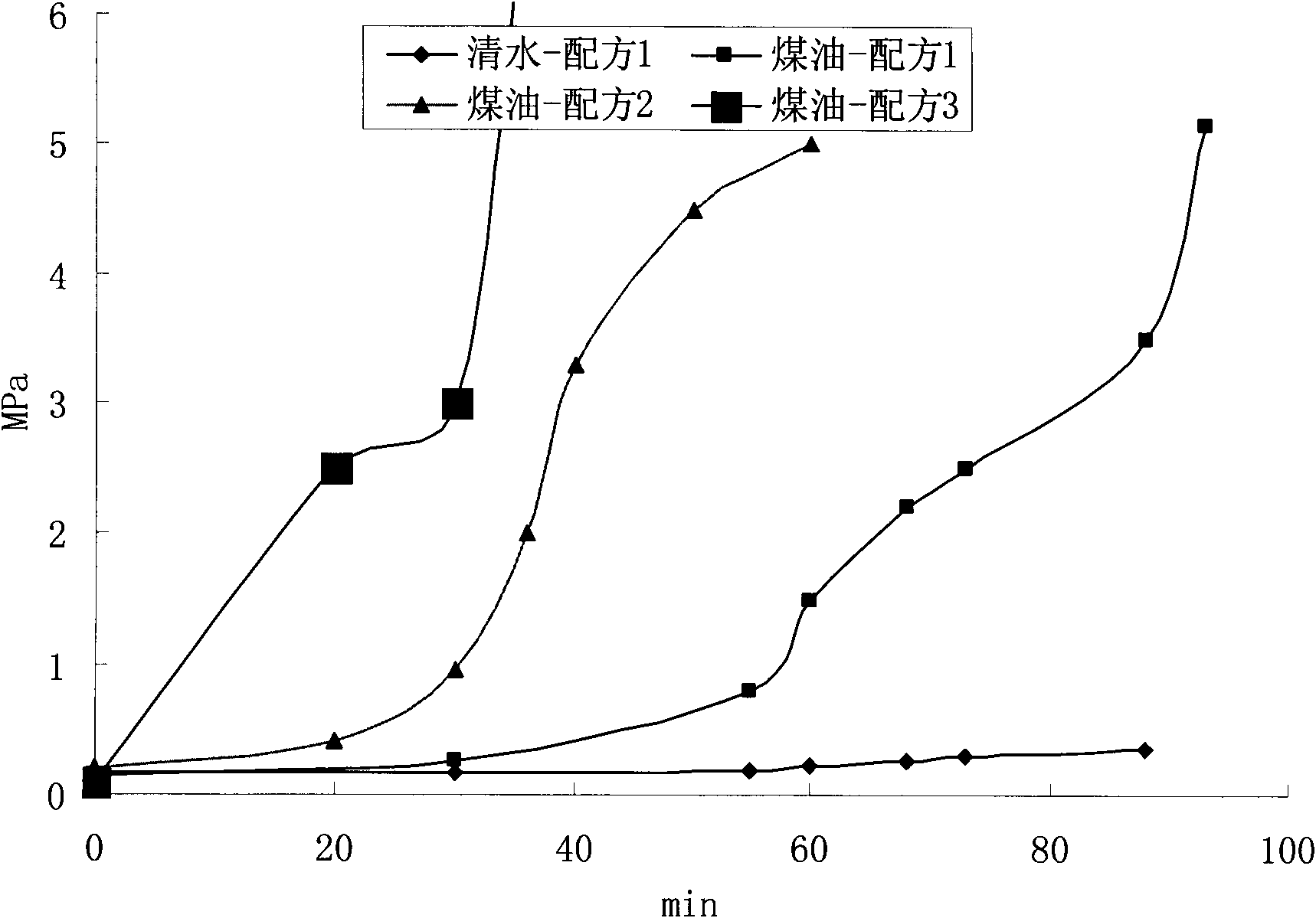
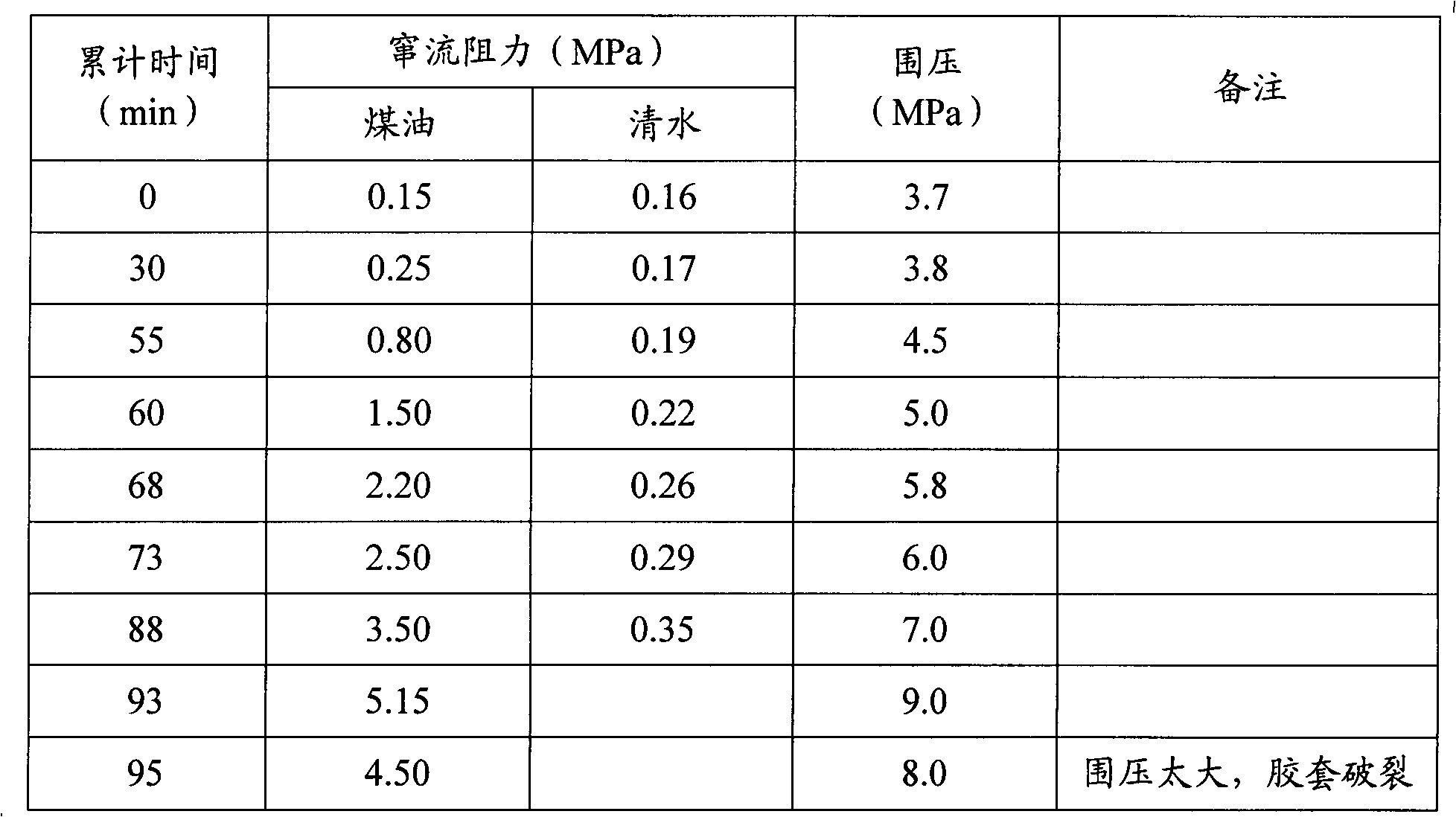
[0026] Table 1 The cross-flow plugging test data of Example 1 (test tem...

Embodiment 2

[0029] The cement slurry system used in the experiment is as follows:

[0030] 800g Xinjiang G grade oil well cement + 3% WG + 1.2% LT-2 + 0.6% SXY-2 + 0.2% ST200R + 45% water

[0031] The specific additives in the formula are: WG is micro silicon, LT-2 is fluid loss reducer, SXY-2 is dispersant, and ST200R is retarder.

[0032] The above cement slurry system adopts the mass percentage of each admixture and cement, and the density of the cement slurry is 1.89g / cm 3 .

[0033] In the case of high-speed stirring, an oil-absorbing resin with a particle size of 80 meshes, accounting for 2% of the total mass of the cement solid phase, was mixed into the above-mentioned cement slurry. The oil-absorbing resin in this example is also based on methacrylate and styrene. Body, ethylene glycol acrylate as crosslinking agent, and the super oil-absorbing resin synthesized by suspension polymerization.

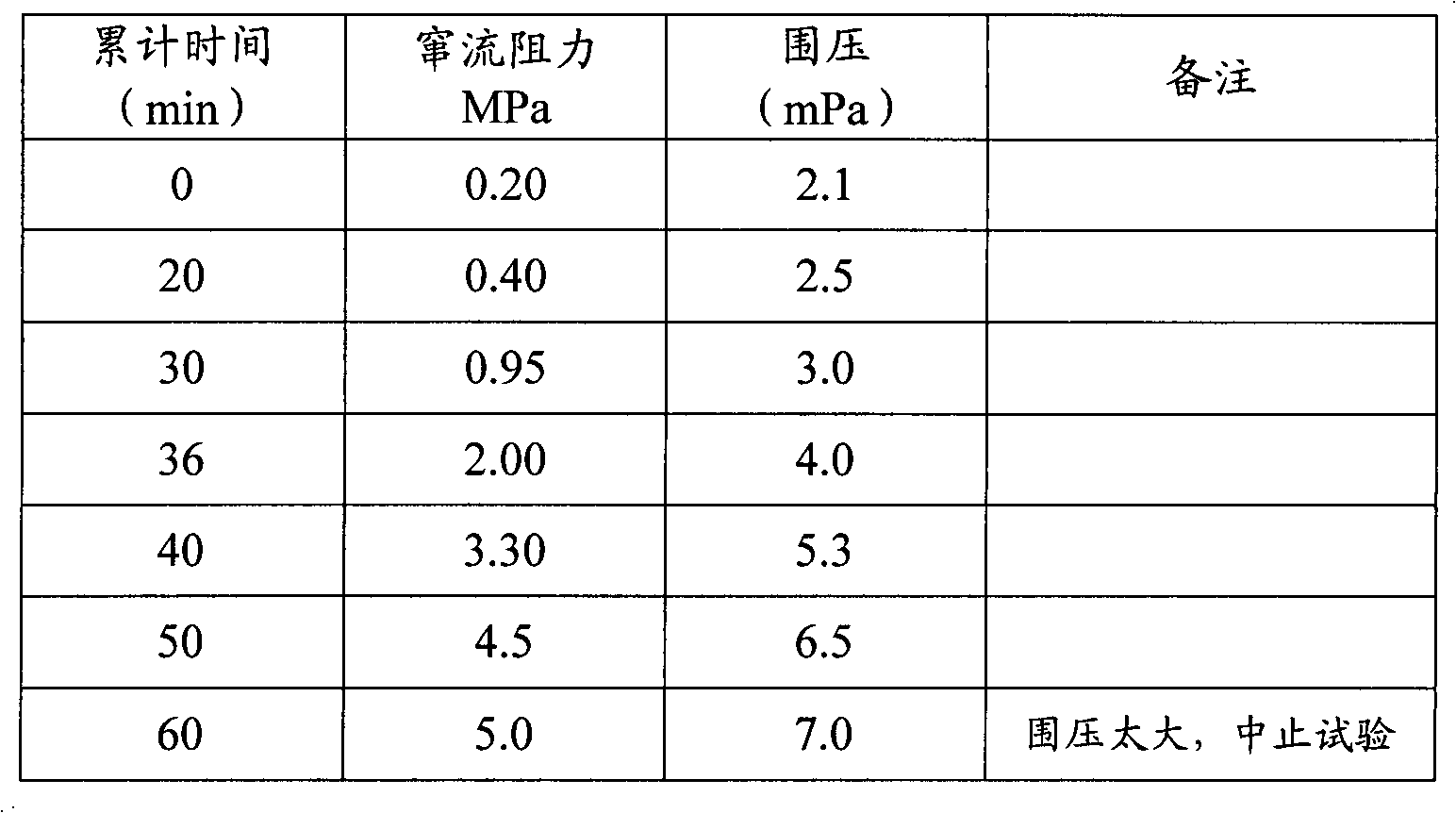
[0034] Table 2 Example 2 kerosene channeling plugging test data (test temperature 27°...

Embodiment 3

[0037] The cement slurry system used in the experiment is as follows:

[0038] 800g Xinjiang G grade oil well cement + 105% Fe 2 o 3 +3%WG+(25%D600G+1.5%D080A+2%D701+0.5%D175)+57%Water

[0039] The additives in the formula are: WG is micro silicon, D600G is fluid loss reducer, D080A is dispersant, D701 is stabilizer, and D175 is defoamer.

[0040] The above cement slurry system adopts the mass percentage of each admixture and cement, and the cement slurry density is 2.40g / cm 3 .

[0041] In the case of high-speed stirring, an oil-absorbing resin with a particle size of 80 meshes, accounting for 3% of the total mass of the cement solid phase, was mixed into the above cement slurry. The oil-absorbing resin in this example is also based on methacrylate and styrene. Body, ethylene glycol acrylate as crosslinking agent, and the super oil-absorbing resin synthesized by suspension polymerization.

[0042] Table 3 Example 3 kerosene channeling plugging test data (test temperature...


PUM

PropertyMeasurementUnit
particle size (mesh)aaaaaaaaaa
densityaaaaaaaaaa

Abstract

The invention relates to a method for enhancing oil well cement slurry for petroleum and natural gas well cementation. The method is mainly characterized in that: an oil absorbing expansion component such as oil absorbing component or the like in an amount which is 0.1 to 3 percent of the total mass of the solid phase and with the particle diameter of 40 to 320 meshes is added into the oil well cement slurry, and the oil absorbing expansion component and the oil well cement slurry are fully stirred; and by using the characteristic that the volume of the oil absorbing expansion component is expanded in oil or after oil absorption, the capability of the oil well cement slurry on plugging micro cracks and micro annular clearances so as to reduce annular cross flow is improved. The method is simple, does not need additional equipment, is favorable for field construction, has wide main material sources and low cost, and can effectively solve the problems of micro cracks in cement stones and/or micro annular clearances on two well cementation interfaces and cross flow of gas, oil and water among underground layers or flow on the ground due to poor initial well cementation quality, influence of subsequent operation on the well cementation quality and change of temperature and pressure in a shaft.

Description

technical field [0001] The invention relates to a method for strengthening oil well cement slurry in oil and gas well cementing, especially by adding oil-absorbing resin and other oil-absorbing swelling components into the oil-well cement slurry, and utilizing the volume expansion of the oil-absorbing swelling component after encountering oil and absorbing oil It is an oil well cement slurry enhancement method that improves the ability of oil well cement slurry to seal micro-cracks and micro-annulus gaps, thereby reducing the problem of annular channeling. Background technique [0002] The main purpose of well cementing is to achieve good interlayer isolation between formations to be isolated, so as to prevent oil, gas and water from flowing between layers or to the ground. [0003] However, well cementing is an underground system engineering with strong concealment, many uncertain factors, and many influencing factors. It is becoming more and more difficult to obtain suffi...

Claims


Application Information

Patent Timeline
Patent Type & Authority Applications(China)
IPC IPC(8): C09K8/467
Inventor 张兴国陈若铭苏洪生黄文红郑永生杨吉祥王云鄢锐
Owner 中国石油集团西部钻探工程有限公司克拉玛依钻井工艺研究院
Why Eureka
Try Eureka