Special bus duct for wind power

A busway and wind power technology, applied in the field of megawatt-level grid-connected wind power generation, can solve the problems of limited carrying capacity of a single conductor, hidden dangers, and difficult displacement control, etc., and achieve the reduction of the number of theoretical fault points, high structural strength and rigidity , The effect of reducing the installation workload

Inactive Publication Date: 2011-06-15
LIAONING JINBANG ELECTRIC
View PDF6 Cites 17 Cited by
  • Summary
  • Abstract
  • Description
  • Claims
  • Application Information

AI Technical Summary

Problems solved by technology

The assembly structure of the conventional busbar assembled busway, especially the connection structure of its joints, is a hard-bar overlapping rigid structure, which is suitable for installation and use in a static mechanical environment (such as in a building) and can maintain long-term structural stability. , but it is not suitable for long-term use under the dynamic load of wind power towers. It will inevitably cause loosening and misalignment of the connection parts and the insulation assembly structure of the body, which will bring hidden dangers or accidents to the power transmission of the busway. At present, there have been accidents in similar projects.
[0004] 2) The current-carrying conductors in the current conventional busbar assembly busway structure generally use rectangular busbars (aluminum or copper bars), and their electric energy carrying capacity is affected by their cross-sectional size, AC skin effect and conductor proximity effect. The carrying capacity of conductors is limited, and a single-phase multi-conductor structure must be formed in the case of large capacity, which results in a large busway structure; and the current and future wind turbines have been developed in the direction of large capacity, and their output current reaches 2000A ~ 3000A Above, the conventional rectangular busway busbars of this current level need to be equipped with double rows, the shape of the busbar is larger, and the requirements for the connection parts are higher, but this structure makes it more inconvenient and hidden dangers to install and use in the wind power tower
[0005] 3) The conventional busbar assembly busway currently used in the wind power industry has an air-insulated insulation structure, and its single piece length is affected by the factory's processing technology. The longest process can only be about 3m, not only the installation cycle is relatively long , and it makes too many connection points inside the wind power tower (compared with the general wind power cable outlet), which not only increases the contact resistance at the joint, but also in the case of wind power operation, the degree of influence of dynamic load at each connection point Inconsistent, the resulting displacement is not easy to control, which virtually increases the hidden danger of accidents; the structural strength and rigidity of the rectangular busbar are relatively low, and its bending strength is anisotropic due to the different forms of its installation facade, so the structure It is not conducive to the isotropic randomness of the wind power swing of the wind power tower in the natural environment in the wild; the accumulation of abnormal displacement at the overlapping surface of the rectangular busbar is enough to reduce the power transmission quality of the wind power output circuit, and even cause accidents; the wind power generation environment is different from Ordinary building installation sites have long been in an unattended and maintenance-free state, and the pursuit of high product reliability is its highest goal. Therefore, it is necessary to develop a new type of structural busway to solve the above defects and make it suitable for wind power.

Method used


Image

  • Special bus duct for wind power
  • Special bus duct for wind power
  • Special bus duct for wind power

Examples


Embodiment Construction

[0021] The busway dedicated to wind power of the present invention will be described in further detail below in conjunction with the accompanying drawings:

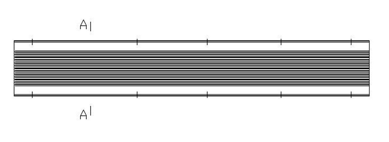
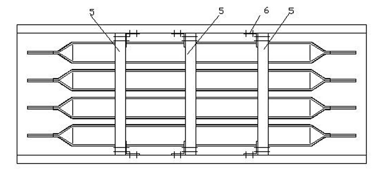
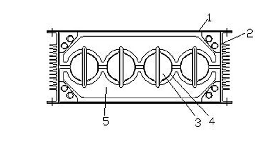
[0022] Such as figure 1 , figure 2 , image 3 , Figure 4 , Figure 5 , Figure 6 , Figure 8 As shown, the busway dedicated to wind power in the present invention includes a busway casing, a multiphase busbar conductor 3, a covering insulation layer 4, an insulating support member 5, a fixing member 6, a conductor flexible connector 7 and a shell flexible connector 8, and the connection method Lan 9;

[0023] The bus duct housing includes upper and lower cover plates and front and rear side plates, the inner length direction of the bus duct housing runs through, and the cover plate 1 and the side plate 2 are fixed by riveting or bolts, and the sealing performance of the riveting is better Good; the cover plate 1 is a galvanized steel plate, the side plate 2 is U-shaped, and there are cooling teeth in the U mouth,...


PUM


Abstract

The invention provides a special bus duct for wind power, comprising a multiphase bus tube conductor (3), an insulating support (5), a fixed block (6), a conductor flexibility connecting piece (7) and a housing flexibility connecting piece (8), wherein the multiphase bus tube conductor (3) is hollow, and the ends of the multiphase bus tube conductor (3) are suppressed into a linear nose shape. The special bus duct utilizes the advantages of small alternating current (AC) skin effect coefficient and preferable electro-conductibility of a hollow pipe conductor, so that the appearance of a large-current bus duct conductor is minimized, and a tubular conductor structure has higher structural strength and rigidity compared with a rectangle conductor structure, thus ensuring the stability of the bus duct conductor and the insulating structure of the bus duct conductor in an irregular pneumatic environment. In the special bus duct, a rigid connecting structure at a joint of a commonly-used bus duct is changed into a flexible connecting structure, thus a capacity that a bus duct structure adapts to a wind turbine tower structure to bear irregular air is improved. The special bus duct can be applied to electric energy output circuits of different high-capacity and synchronizing wind power generator sets.

Description

technical field [0001] The invention belongs to the technical field of megawatt-level grid-connected wind power generation, and in particular relates to a busway dedicated to wind power. Background technique [0002] At present, the application and development prospects of domestic new energy wind turbines are broad, and the capacity of megawatt-scale grid-connected wind turbines is also tending to be large, from 1.2-1.5MW for a single unit to a larger 2.0-3.5MW or even 5MW. It brings the output current of a single unit (the output voltage of most wind turbines is low voltage 690V) from 1000A to 1600A to a higher value of 2000A to 3000A, which brings more disadvantages to the laying and installation of the original wind power outlet cables. In terms of electrical performance The disadvantages are gradually becoming apparent. In this context, the insulated transmission busway assembled by conventional busbars is gradually applied in the field of wind power and wind power. T...

Claims


Application Information

Patent Timeline
Patent Type & Authority Applications(China)
IPC IPC(8): H02G5/02
Inventor 王建平
Owner LIAONING JINBANG ELECTRIC
Why Eureka
Try Eureka