
Multi-beam laser heterodyne distance measurement device and method for measuring young modulus by adopting device

A technology of laser heterodyne and distance measurement, which is applied in the field of testing, can solve the problem of a single parameter value to be measured, and achieve the effect of fast measurement speed, convenient operation and good linearity

Inactive Publication Date: 2011-09-07
HARBIN INST OF TECH
View PDF8 Cites 14 Cited by
  • Summary
  • Abstract
  • Description
  • Claims
  • Application Information

AI Technical Summary

Problems solved by technology

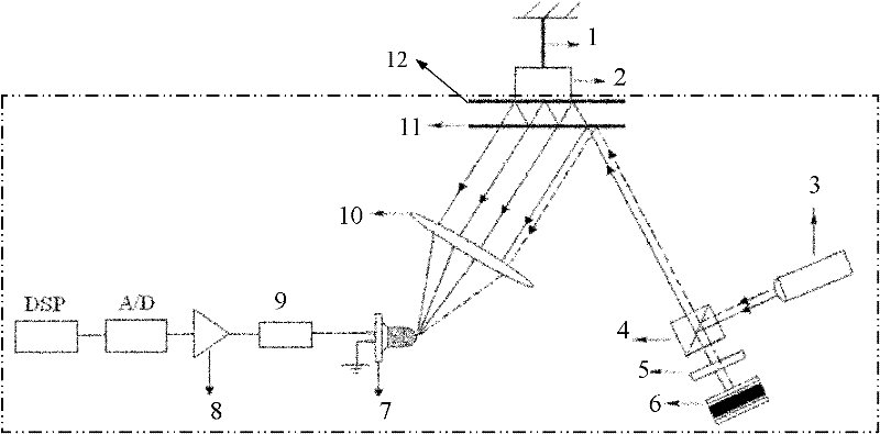
[0004] In order to solve the problem that the existing traditional heterodyne interferometry can only obtain a single value of the parameter to be measured, the present invention proposes a multi-beam laser heterodyne distance measurement device and a method for measuring Young's modulus using the device

Method used


Image

  • Multi-beam laser heterodyne distance measurement device and method for measuring young modulus by adopting device
  • Multi-beam laser heterodyne distance measurement device and method for measuring young modulus by adopting device
  • Multi-beam laser heterodyne distance measurement device and method for measuring young modulus by adopting device

Examples


specific Embodiment approach 1

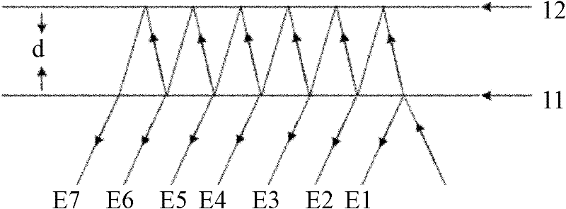
[0023] Embodiment 1. The device for measuring distance by multi-beam laser heterodyne described in this embodiment is composed of H 0 Composition of solid-state laser 3, plane mirror 12, quarter-wave plate 5, galvanometer 6, galvanometer driving power supply, polarizing beam splitter 4, converging lens 10, thin glass plate 11, photodetector 7 and signal processing system , the vibrating mirror drive power supply is used to drive the vibrating mirror 6 to vibrate; the thin glass plate 11 is in a fixed position, and a plane reflector 12 is set on one side of the thin glass plate 11 at a distance d, and the distance between the thin glass plate 11 and the plane reflector 12 The reflective surfaces are opposite and parallel to each other, H 0 The solid-state laser 3, the quarter-wave plate 5, the vibrating mirror 6, the polarizing beam splitter 4, the converging lens 10, and the photodetector 7 are all located under the thin glass plate 11, and the H 0 The solid-state laser 3 emi...

specific Embodiment approach 2

[0039] Specific embodiment two, described in this embodiment is to adopt the device for measuring Young's modulus of the multi-beam laser heterodyne described in specific embodiment one to realize the method for measuring Young's modulus, and the process of this method is:

[0040] Step 1. Hang a metal wire to be tested with a length L and an average diameter of r on a fixed support, and the lower end is fixedly connected with a weight. Under the action of the weight itself, the weight exerts a pulling force F on the steel wire to be tested. To make the steel wire generate internal stress; the bottom of the weight is fixedly connected to the bottom surface of the plane mirror 12, and then the laser is turned on;

[0041] Step 2, the signal processing system collects the signal output by the photodetector 7, and obtains a distance parameter, and records the distance parameter when the plane reflector 12 is in a static state;

[0042] Step 3, increase the quality m of the weight...


PUM


Abstract

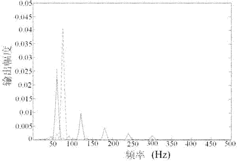
The invention discloses a multi-beam heterodyne distance measurement device and a method for measuring a young modulus by adopting the device, which relate to the technical field of testing and aim to solve the problem that only a single parameter value to be tested can be obtained by the conventional heterodyne interference method. The device and the method are implemented based on a laser heterodyne technology and Doppler effects. The device introduces a galvanometer into a light path to attach optical frequency to optical signals incident at different moments, and then light reflected by athin glass plate and the light reflected by a planar mirror for many times produce a multi-beam heterodyne interference signal when interference conditions are met, thereby successfully modulating information to be tested in a frequency difference of an intermediate frequency heterodyne signal. In the method, a plurality of frequency values comprising the information about metal length change amounts are obtained at the same time in a frequency domain, the signal is demodulated to obtain a plurality of length change amounts, and weighted averaging is performed to obtain the accurate amount ofchange, made along with temperature, of a sample. In a simulation experiment performed by taking a carbon steel wire as an example, a relative error of young modulus measurement is only 0.3 percent.

Description

technical field [0001] The invention relates to the technical field of testing, in particular to a method for measuring distance and Young's elastic modulus of materials. Background technique [0002] Young's modulus of elasticity reflects the relationship between material deformation and internal stress. When a material is subjected to external force, it must be deformed. The ratio of its internal stress and strain (ie relative deformation) is called Young's modulus of elasticity. An important physical quantity of material properties is an important parameter in the selection of mechanical components in engineering technology. In recent years, in engineering measurement technology, optical rod method, optical fiber sensor method, CCD method, interference method, stretching method and diffraction method are mostly used, but these methods have more indirect measurements, larger accidental errors, and require A large amount of data processing is carried out. Therefore, the me...

Claims


Application Information

Patent Timeline
IPC IPC(8): G01S17/08G01B11/16G01N3/14
Inventor 李彦超王春晖高龙曲杨
Owner HARBIN INST OF TECH
Learn More