Method for purifying tail gas of flue gas carbon dioxide collecting system through rotating flow and device thereof

A carbon dioxide and flue gas technology, applied in chemical instruments and methods, separation methods, climate sustainability, etc., can solve problems such as uneconomical, economic benefit impact, and increased operating costs, so as to reduce emissions and avoid entrainment Damage and prevention of atmospheric environment hazards

Active Publication Date: 2013-04-17
SHANGHAI HUACHANG ENVIRONMENT PROTECTION +1
View PDF4 Cites 0 Cited by
  • Summary
  • Abstract
  • Description
  • Claims
  • Application Information

AI Technical Summary

Problems solved by technology

This also makes the oxyfuel combustion capture technology not have much economic advantage
[0010] In the current flue gas carbon dioxide capture system, the flue gas is absorbed and captured by the carbon dioxide absorbent in the absorption tower to generate the tail gas of the carbon dioxide capture system, which contains a large number of aerosol particles, especially PM2 .5 particles, if they are not captured and removed before the exhaust gas is discharged into the atmosphere, it will not only cause serious harm to the atmospheric environment, but also cause entrainment and running loss of the washing liquid, resulting in a large operating cost of the entire flue gas carbon dioxide capture device Therefore, how to recycle these aerosol particles is a major technical problem in the field of energy and environment.
The existing aerosol particle capture methods include rotary flow separator and electric trap. The pressure drop of the former is generally 500Pa~600Pa, even as high as 1000Pa. The existing technology cannot be used for flue gas carbon dioxide capture. In the collection system, first, the pressure drop is too high, and the flue gas tail gas at the top of the absorption tower cannot support such a high pressure drop consumption; second, if the existing cyclone separator technology is to be used, the flue gas tail gas must be increased pressure, both complex and uneconomical
For the electric trap, because the flue gas tail gas has a large water content, it is easy to cause safety hazards, and the cost is too high, so there is no economical and applicable electric trap in the project

Method used


Image

  • Method for purifying tail gas of flue gas carbon dioxide collecting system through rotating flow and device thereof

Examples


Embodiment Construction

[0027] In order to make the technical means, creative features, goals and effects achieved by the present invention easy to understand, the present invention will be further described below in conjunction with specific illustrations.

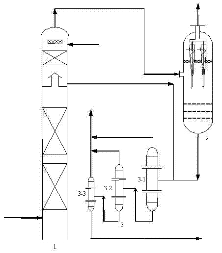
[0028] Such as figure 1 As shown, the absorption tower 1 located at the forefront of the device is used to absorb and capture the carbon dioxide components in the flue gas, and remove the gas components such as sulfur dioxide and nitrogen oxides entrained in the tail gas.

[0029] The ultra-low pressure drop swirl flow separator 2 connected to the tail gas outlet at the top of the absorption tower 1 is used for swirl flow separation and recovery of aerosol particles entrained in the tail gas.

[0030] The liquid-solid micro-swirl flow separator group 3 connected to the wash liquid outlet of the ultra-low pressure drop swirl flow separator 2 and the wash liquid outlet of the absorption tower 1 is used for swirl flow separation of solid particles ...


PUM


Abstract

The invention relates to a method for purifying tail gas of flue gas carbon dioxide collecting system through rotating flow, comprising the following steps: carrying out rotating flow separation with ultra-low pressure drop on the tail gas exhausted from the top of a carbon dioxide absorption tower in order to eliminate aerosol particles in the tail gas; and returning recovered washing liquid into a washing liquid system after liquid-solid micro-rotating flow separation. The method has advanced technique, long continuous operation period, small volume and low fault rate, thereby reducing the discharge amount of aerosol particles, preventing the washing liquid from being lost, preventing the atmosphere environment from being damaged by chemical products, and inhibiting or even eliminating the smoke spreading in cold seam and the corrosion on the device. The invention further provides a device used for applying the method; and the device is convenient to operate and easy to control, andachieves and satisfies the requirement to industrial production and environment coordination.

Description

technical field [0001] The invention relates to the field of energy and environment, in particular to a swirling flow purification method for tail gas of a flue gas carbon dioxide capture system, and also relates to a swirling flow purification device for flue gas carbon dioxide capture tail gas. Background technique [0002] Today, 80% of the world's energy comes from fossil fuels such as coal, oil and natural gas. Although the cost of hydropower and nuclear energy is not high, environmental conditions limit the scale of their development. As for new energy sources such as wind energy, solar energy, and biomass energy, although the prospect of environmental protection is gratifying, due to the constraints of objective factors such as high cost and immature technology, these new energy sources are still in the exploratory stage to completely replace traditional fossil energy sources, and truly achieve large-scale commercialization. It will take a long time to develop. Ther...

Claims


Application Information

Patent Timeline
Patent Type & Authority Patents(China)
IPC IPC(8): B01D53/78B01D53/62B01D45/16B01D21/26
CPCY02P70/34Y02P70/10Y02A50/20
Inventor 马良毛松柏汪华林叶宁许德建吕文杰黄渊李剑平
Owner SHANGHAI HUACHANG ENVIRONMENT PROTECTION
Why Eureka
Try Eureka