Manufacture process and application technical process of energy-saving and emission-reducing high-gradient magnetic separating machine with ultrastrong magnetic field

A high-gradient magnetic separation, energy-saving and emission-reducing technology, which is applied in high-gradient magnetic separators, magnetic/electric field water/sewage treatment, etc., can solve the problem of difficult cleaning of ore-discharging magnetic bonding, large consumption of production materials, and mechanical inclusions And other issues

Inactive Publication Date: 2011-10-12
潘树明
View PDF4 Cites 10 Cited by
  • Summary
  • Abstract
  • Description
  • Claims
  • Application Information

AI Technical Summary

Problems solved by technology

In the development, the problems existing in the current high-gradient magnetic separation equipment are that the sorting space is narrow, the production consumes a large amount of materials, the magnetic system structure is not perfect, the magnetic bonding of t

Method used


Image

  • Manufacture process and application technical process of energy-saving and emission-reducing high-gradient magnetic separating machine with ultrastrong magnetic field
  • Manufacture process and application technical process of energy-saving and emission-reducing high-gradient magnetic separating machine with ultrastrong magnetic field
  • Manufacture process and application technical process of energy-saving and emission-reducing high-gradient magnetic separating machine with ultrastrong magnetic field

Examples


Embodiment 1

[0066] Anshan-depleted magnetite ore, using wet magnetic separation process, the ore is mainly magnetite, containing a small amount of hematite, the gangue minerals are mainly quartz, containing a small amount of hornblende, margin stone, calcite, mica, green curtain Stone and apatite, the ore is in a banded structure, composed of interlayers of iron mineral layers and gangue layers. The average thickness of iron ore strips is 0.5-0.8 mm, and the average thickness of non-iron ore strips is 0.2-0.4 mm. The iron minerals are fine-grained inlaid cloth, the inlaid cloth particle size is about 0.1 mm, the ore specific gravity is 3.3-3.5, the ore Platinum degree is 8-12, and the magnetic rate is about 33-36%.

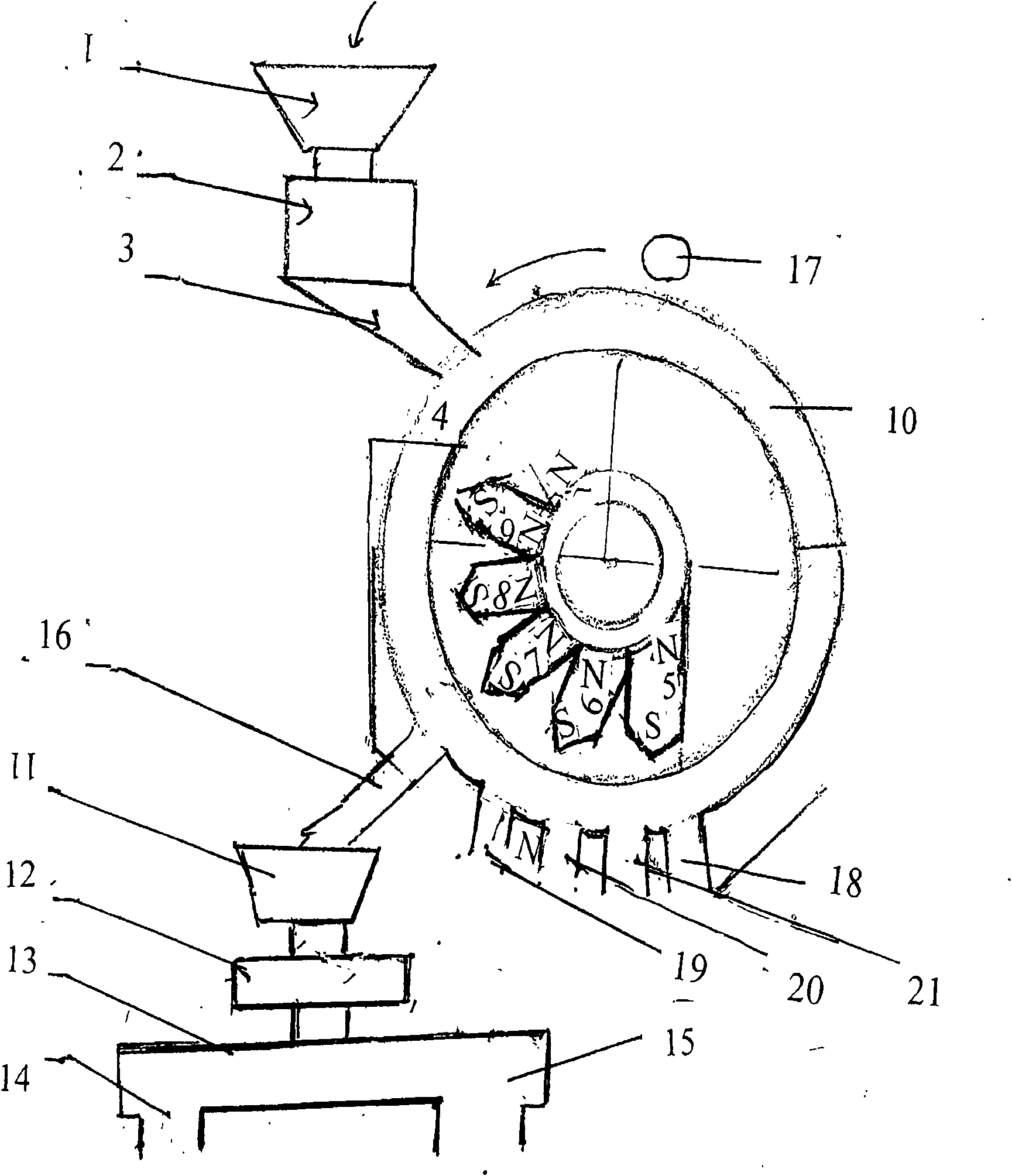
[0067] Raw ore is ball milled after coarse crushing and intermediate crushing. After sieving, it is graded - 200 mesh 75%, and enters this high-gradient magnetic separation and separation. Magnetically separate the magnetic concentrate into the press Figure 4 The process f...

Embodiment 2

[0069] Raw material composition is with embodiment 1, and its preparation technology is with embodiment 1.

[0070] Described rare earth permanent magnet material: adopt high-performance Nd-Fe-B series permanent magnet, kind is: N50M, N52, ferrite adopts anisotropic strontium ferrite: maximum magnetic energy product (BH) m=26KJ / m 3 , coercive force Hc=260KA / m, intrinsic coercive force is 275KA / m, anisotropic alnico permanent magnet, maximum energy product (BH)m=44KJ / m 3 , coercive force 50KA / m, other preparation technology and application are identical with embodiment 1.


PUM

PropertyMeasurementUnit
Thicknessaaaaaaaaaa
Thicknessaaaaaaaaaa
Maximum energy productaaaaaaaaaa

Abstract

The invention provides a manufacture process and an application technical process of a high-gradient magnetic separating machine with an ultrastrong magnetic field. Set magnetic separating magnet materials comprise ferrite, alnico, SmFeN and a rare earth permanent magnet material. A magnetic separating chamber is made of non-magnet-conducting materials, a slurry outlet and a slurry inlet are respectively arranged on the upper part and the lower part of the magnetic separating chamber, and magnetic separating media put in the separating chamber are steel wool. An emission-reducing and energy-saving ball mill saves energy and reduces the emission of exhaust gas. Multiple times of fine separation are adopted in the technical process for improving iron content. After tailings are ground by using the ball mill to reduce the iron content in the tailings, the tailings enter a sorting machine, and a high-gradient magnetic separating technical process of stainless steel wool is adopted for treating waste water. The magnetic separation and mine sewage treatment technical indexes of the process provided by the invention reach an advanced level.

Description

Technical field: [0001] The invention relates to a magnetic separation equipment pole preparation process for magnetic separation and its application technology, in particular to an energy-saving emission reduction ultra-strong magnetic field high-gradient magnetic separation equipment technology and its application technology in a magnetic separator. Background technique: [0002] The new theory and application technology of strong magnetic field and high gradient magnetic separation is a new high-tech technology. The application field is doubled, and on the basis of improving the iron grade of the concentrate in the original magnetite mine, it can be used to separate iron, titanium, tungsten, tin, molybdenum, copper, tantalum, niobium and other multi-metallic minerals. , It can also be applied to the extraction of mica, quartz, feldspar, calcite, fluorite, molding sand, kaolin, talc, and non-metallic minerals containing S, As, Bi, etc. [0003] At present, some countries ...

Claims


Application Information

Patent Timeline
IPC IPC(8): B03C1/025B03C1/033B03C1/031C02F1/48
Inventor 潘树明
Owner 潘树明
Why Eureka
Try Eureka