Device and method for removing sulfur dioxide and dioxin from sintering flue gas

A technology of sintering flue gas and flue gas, which is applied in the field of flue gas purification, can solve the problems of system investment, high operating cost, complicated activated carbon/coke process, and easy spontaneous combustion of activated carbon/coke, and achieves small footprint, lightened burden, Effect of reducing particle concentration

Inactive Publication Date: 2011-11-02
INST OF PROCESS ENG CHINESE ACAD OF SCI +1
View PDF6 Cites 48 Cited by
  • Summary
  • Abstract
  • Description
  • Claims
  • Application Information

AI Technical Summary

Problems solved by technology

The activated carbon / coke process is complicated, the desorption process consumes a lot of energy, the activated carbon / coke is prone to spontaneous combustion, and the system investment and operation costs are very high
The European MEROS technology is used to remove sulfur dioxide and dioxins from sintering flue gas. In this technology, carbon-based adsorbents and desulfurizers (baking soda or slaked lime) are reversely injected into the sintering waste gas stream to remove heavy metals and organic matter. Composition, the exhaust gas is passed through the conditioning reactor, sprayed with water for cooling and humidification to speed up the removal of SO 2 The reaction rate with other acid gas components, the exhaust gas flow out of the regulating reactor passes through the bag filter to separate the dust, the disadvantage of MEROS is that the desulfurization efficiency is not high, and the desulfurization rate can only reach 80% when the calcium-sulfur ratio is 4 after adding slaked lime; The desulfurization rate can reach 80%-85% by adding sodium bicarbonate, but the cost is higher

Method used


Image

  • Device and method for removing sulfur dioxide and dioxin from sintering flue gas
  • Device and method for removing sulfur dioxide and dioxin from sintering flue gas
  • Device and method for removing sulfur dioxide and dioxin from sintering flue gas

Examples


Embodiment Construction

[0038] Further detailed description will be given below in conjunction with the accompanying drawings and specific embodiments.

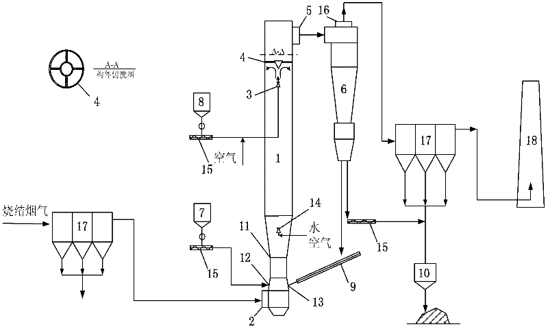
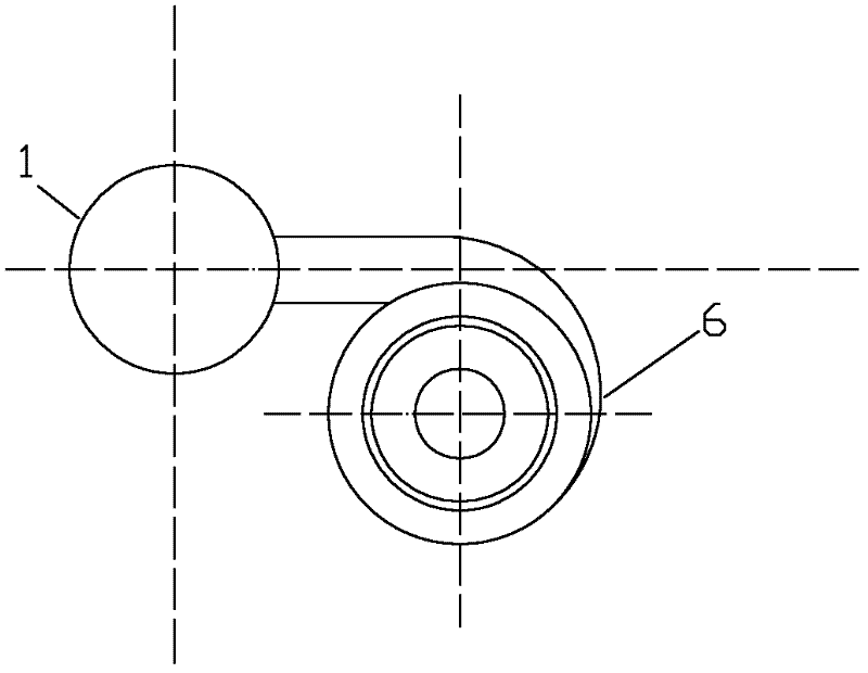
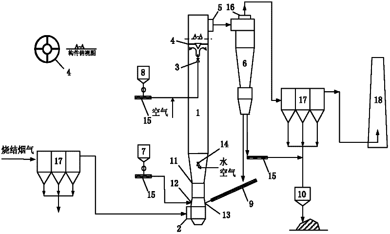
[0039] Such as figure 1 Shown, this figure is the sintering flue gas SO provided by the present invention 2 and dioxin removal device. Including a circulating fluidized bed absorption tower (1), a flue gas inlet (2) is provided at the bottom of the absorption tower (1), and an activated carbon / coke nozzle (3) is arranged in the upper part of the absorption tower (1), facing the activated carbon / coke nozzle (3) Conical member (4) is set, and the top of absorption tower (1) is provided with flue gas outlet (5), and flue gas outlet (5) is communicated with cyclone separator (6) by pipeline; It is characterized in that: also includes Desulfurizer bin (7), activated carbon / coke bin (8), screw feeder (9), ash bin (10); wherein the lower part of the circulating fluidized bed absorption tower (1) adopts a Venturi structure (11) , the Venturi structure (1...


PUM


Abstract

The invention relates to a device and a method for removing sulfur dioxide and dioxin from sintering flue gas. The lower part of an absorption tower of the device has a Venturi structure; a Venturi shrinkage section is provided with a desulfurizing agent inlet and a circulating ash inlet; a Venturi expansion section is provided with a water spray nozzle; the upper middle part of the absorption tower is provided with an active carbon/coke nozzle and a conical component is arranged opposite to the nozzle; the upper part; the upper part of the absorption tower is provided with a flue gas outlet which is connected with a radially arranged cyclone separator; a hoper at the lower end of the cyclone separator is provided with two outlets, one outlet is connected with an ash bin, and the other outlet is connected with a circulating ash inlet through a spiral return device; a gas outlet on the top of the cyclone separator is communicated with an inlet of a deduster; and a gas outlet of the deduster is connected with a chimney. The sintering flue gas containing SO2 and dioxin enters the absorption tower through the Venturi, and is mixed with slaked lime Ca(OH)2, atomized water and active carbon/coke, which are sprayed in the absorption tower, the Ca(OH)2 absorbs the SO2 under the action of the atomized water and the active carbon/coke absorbs the dioxin to cooperatively remove the two pollutants.

Description

technical field [0001] The invention belongs to the field of flue gas purification, and in particular relates to a device and method for desulfurization and dioxin removal of flue gas of a steel sintering machine. Background technique [0002] Sulfur dioxide (SO 2 ) and dioxins are two main pollutants in the flue gas of steel sintering machines. my country's iron and steel industry SO 2 The emissions are second only to the power industry and industrial boilers, ranking third, and the SO emissions from the iron and steel industry 2 50%-70% of it comes from the sintering process, sintering flue gas SO 2 Emission reduction has become my country's SO 2 The focus of emission control. Dioxin-like pollutants are organic pollutants that are clearly required to be controlled and reduced in the Stockholm Convention on Persistent Organic Pollutants (POPs). my country has officially implemented the Convention on November 11, 2004. According to the data in 2004, the atmospheric di...

Claims


Application Information

Patent Timeline
Patent Type & Authority Applications(China)
IPC IPC(8): B01D53/83B01D53/96B01D50/00B01D53/50B01D53/72
Inventor 朱廷钰叶猛徐文青王雪李玉然荆鹏飞刘文
Owner INST OF PROCESS ENG CHINESE ACAD OF SCI
Why Eureka
Try Eureka