
Trichlorosilane vaporization device

A trichlorosilane and vaporization device technology, applied in the direction of silicon, etc., can solve the problems affecting product quality, fluctuations in proportion, uneven mixing, etc., and achieve the effect of good appearance quality of crystal grains, avoiding liquid foam entrainment, and stable proportioning

Inactive Publication Date: 2011-12-21
SICHUAN XINGUANG SILICON TECH
View PDF5 Cites 5 Cited by
  • Summary
  • Abstract
  • Description
  • Claims
  • Application Information

AI Technical Summary

Problems solved by technology

However, when using this mixing device to vaporize chlorosilane, since the vaporization process of chlorosilane is uncontrollable, when the temperature and pressure of the heat exchanger change, the liquid level of chlorosilane will fluctuate accordingly, and the vaporization amount of chlorosilane will also change accordingly , so there is still an error in the ratio control of the chlorosilane gas and hydrogen that actually enter the reduction furnace
In addition, in this device, both the chlorosilane liquid and the hydrogen enter from the upper part of the heat exchanger, that is, the chlorosilane liquid is sprayed with hydrogen, and a small amount of metal impurity compounds in the chlorosilane will enter the reduction furnace together with the hydrogen, affecting product quality; , the vaporization of chlorosilane is not completely steady state, causing the vaporization amount of chlorosilane to fluctuate, which makes the ratio fluctuate. In addition, the hydrogen gas flows rapidly in the tube side, forming a gas beam, which makes the mixing of hydrogen gas and trichlorosilane gas uneven
The above defects cause fluctuations in the ratio of the raw material mixture and uneven mixing, which ultimately affects the reaction in the reduction furnace

Method used


Image

  • Trichlorosilane vaporization device
  • Trichlorosilane vaporization device
  • Trichlorosilane vaporization device

Examples


Embodiment 1

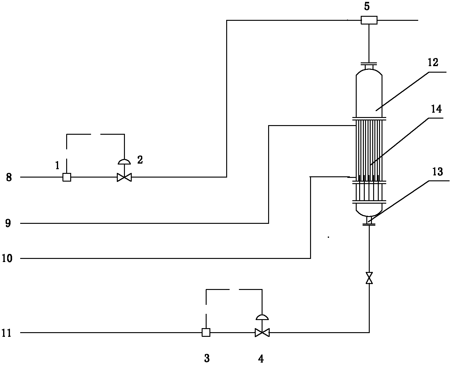
[0042] Such as figure 1 As shown, the trichlorosilane vaporization device listed in this embodiment includes an evaporator 12, a mixer 5, a trichlorosilane liquid delivery pipe, a trichlorosilane gas delivery pipe, and a mixed gas delivery pipe, and the evaporator 12 includes a tube array Type heat exchanger 14, the bottom of evaporator 12 is provided with trichlorosilane liquid inlet 13, and the top is provided with trichlorosilane gas outlet 16, and trichlorosilane liquid inlet 13 is connected with trichlorosilane liquid delivery pipe; The tube side of the type heat exchanger 14 communicates with the trichlorosilane liquid delivery pipe, and the shell side communicates with the pipeline for transporting external circulating water.

[0043] The mixer 5 communicates with the hydrogen delivery pipe, the trichlorosilane gas delivery pipe and the mixed gas delivery pipe respectively.

[0044] The trichlorosilane liquid delivery pipe is provided with a trichlorosilane mass flowm...

Embodiment 2

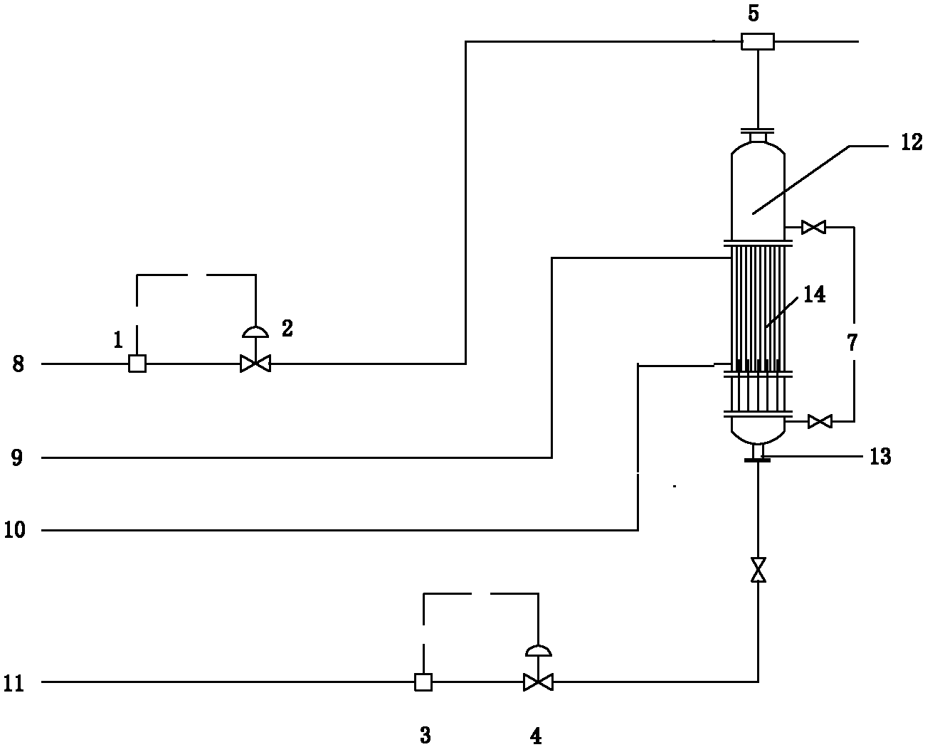
[0054] Such as figure 2 As shown, the trichlorosilane vaporization device listed in this embodiment includes an evaporator 12, a mixer 5, a trichlorosilane liquid delivery pipe, a trichlorosilane gas delivery pipe, and a mixed gas delivery pipe, and the evaporator 12 includes a tube array Type heat exchanger 14, the bottom of evaporator 12 is provided with trichlorosilane liquid inlet 13, the top is provided with trichlorosilane gas outlet 16, and trichlorosilane liquid inlet 13 is connected with trichlorosilane liquid delivery pipe; Evaporator 12 is also provided with a liquid level gauge 7, the liquid level gauge 7 is an internal floating magnetic liquid level gauge, the tube side of the tube-and-tube heat exchanger is connected with the trichlorosilane liquid delivery pipe, and the shell side is connected with the pipeline for transporting the external circulating water connected.

[0055] The mixer 5 communicates with the hydrogen delivery pipe, the trichlorosilane gas d...

Embodiment 3

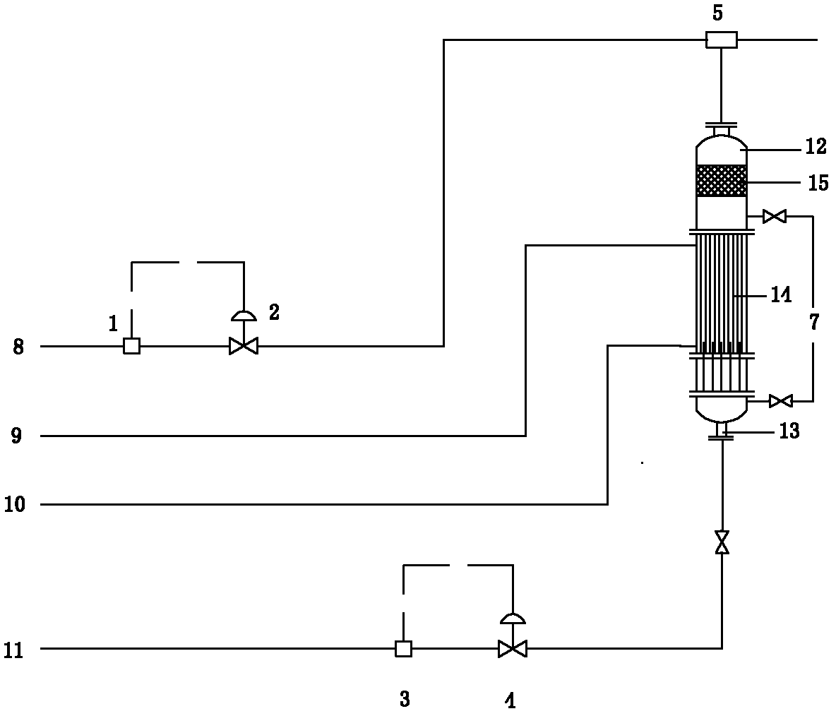
[0059] Such as image 3 As shown, the trichlorosilane vaporization device listed in this embodiment includes an evaporator 12, a mixer 5, a trichlorosilane liquid delivery pipe, a trichlorosilane gas delivery pipe, and a mixed gas delivery pipe, and the evaporator 12 includes a lower The shell and tube heat exchanger 14 and the demister 15 on the top, the bottom of the evaporator 12 is provided with a trichlorosilane liquid inlet 13, the top is provided with a trichlorosilane gas outlet 16, the trichlorosilane liquid inlet 13 is connected with trichlorohydrogen The silicon liquid delivery pipe is connected; the evaporator 12 is also provided with a liquid level gauge 7, the liquid level gauge 7 is an internal floating magnetic liquid level gauge, and the tube side of the tube-and-tube heat exchanger is connected with the trichlorosilane liquid delivery pipe, The shell side communicates with the pipeline for conveying the external circulating water.

[0060] The mixer 5 commun...


PUM


Abstract

The invention relates to a polysilicon production device, in particular to a trichlorosilane vaporization device, and belongs to the technical field of polysilicon production. The trichlorosilane vaporization device of the present invention comprises an evaporator, a hydrogen delivery pipe, a trichlorosilane liquid delivery pipe, a trichlorosilane gas delivery pipe, a mixed gas delivery pipe, and a mixer, and the lower end of the evaporator is provided with trichlorosilane The silicon liquid inlet and the upper end are provided with a trichlorosilane gas outlet; the trichlorosilane liquid inlet is connected with the trichlorosilane liquid conveying pipe; the trichlorosilane liquid conveying pipe and the hydrogen conveying pipe are provided with a meter; the mixer They are respectively connected with the hydrogen gas delivery pipe, the trichlorosilane gas delivery pipe and the mixed gas delivery pipe. Using the trichlorosilane vaporization device of the present invention to vaporize trichlorosilane can obtain a mixed gas with a stable ratio and uniform mixing; the mixing of raw materials is more uniform, which is conducive to the uniform growth of silicon rods in the reduction reaction of the reduction furnace, The appearance quality of the produced crystal grains is better.

Description

technical field [0001] The invention relates to a polysilicon production device, in particular to a trichlorosilane vaporization device, and belongs to the technical field of polysilicon production. Background technique [0002] Polysilicon is the basic raw material of the electronics industry and solar photovoltaic industry. With the rapid development of information technology and solar energy industry, the global demand for polysilicon is growing rapidly, and the market is in short supply. [0003] Polycrystalline silicon (p-Si) is a form of elemental silicon. It is a silicon crystal composed of many silicon atoms and many small grains. According to the purity classification, it can be divided into metallurgical grade polysilicon, solar grade and electronic grade polysilicon. Among them, the purity of solar-grade energy polysilicon products is 99.99-99.9999% (4 to 6 nines), the purity of electronic-grade polysilicon products is above 99.9999%, and the ultra-high purity is ...

Claims


Application Information

Patent Timeline
Patent Type & Authority Applications(China)
IPC IPC(8): C01B33/03
Inventor 刘畅王岭张维刘维
Owner SICHUAN XINGUANG SILICON TECH
Learn More