Method for manufacturing chip oxygen sensor and chip oxygen sensor

A technology of an oxygen sensor and a manufacturing method, which is applied to instruments, scientific instruments, measuring devices, etc., can solve the problems of uneven pressure, long activation time, poor oxygen sensitivity, etc., and achieves a good degree of integration, simple process flow, and activation time. quick effect

Active Publication Date: 2014-04-02
CHERY AUTOMOBILE CO LTD
View PDF5 Cites 0 Cited by
  • Summary
  • Abstract
  • Description
  • Claims
  • Application Information

AI Technical Summary

Problems solved by technology

[0022] First, during the molding and sintering process of the substrate, since the sensor matrix, the reference air channel layer and the heater matrix are relatively thin and brittle, they are easy to break during the preparation process, easy to deform during the sintering process, and the yield is low;
[0023] Second, the uneven pressure during the lamination hot pressing process and improper temperature control during the sintering process can easily lead to blockage of the reference air channel or the substrate is not laminated and hot pressed into one, and the sintered substrate is uneven;
[0024] Third, bond the sintered reference air channel layer with the sintered and coated sensor substrate and the heater substrate as a whole, and apply sealant between the substrate layers It is very difficult to make it have good sealing performance as a whole;
[0025] Fourth, the sensitivity to oxygen is poor at high temperature, and the required activation time is longer

Method used


Image

  • Method for manufacturing chip oxygen sensor and chip oxygen sensor
  • Method for manufacturing chip oxygen sensor and chip oxygen sensor
  • Method for manufacturing chip oxygen sensor and chip oxygen sensor

Examples


Embodiment 1

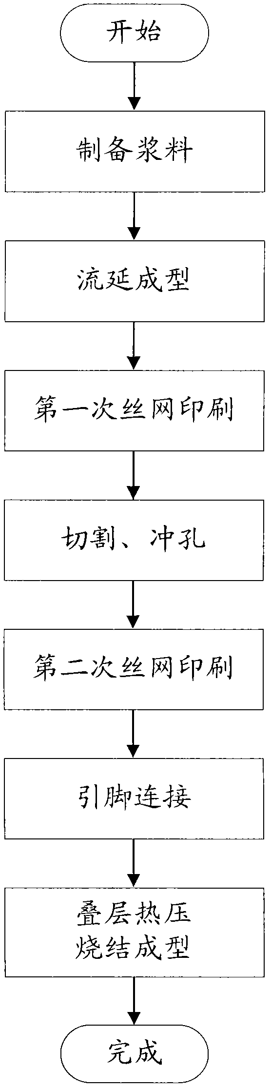
[0069] The manufacturing method of the chip oxygen sensor in this embodiment includes the following steps:

[0070] ①. Preparation of slurry:

[0071] Take by weighing 200g mole fraction of 8% yttrium oxide fully stabilized zirconia powder, place it in a ball mill jar, then add 100g ethanol, 16.67g dibutyl phthalate, 16.67g polyvinyl butyral respectively, Among them, according to mass percentage, zirconia powder accounts for 60%, ethanol accounts for 30%, dibutyl phthalate accounts for 5%, polyvinyl butyral accounts for 5%, and the materials in the ball mill tank are ball milled and mixed for 15 hours , after vacuum defoaming and sieving, a slurry with a viscosity of 906mPa·s is made;

[0072] ②. Tape casting:

[0073] Put the slurry prepared in step ① into a casting machine, use a double scraper to make a membrane with a uniform thickness from the non-water-based slurry placed on the film-forming backing belt, and place the prepared membrane in a solvent atmosphere Dry to ...

Embodiment 2

[0087] The manufacturing method of the chip oxygen sensor in this embodiment includes the following steps:

[0088] ①. Preparation of slurry:

[0089] Weigh 200g of yttrium oxide fully stabilized zirconia powder with a mole fraction of 8%, place it in a ball mill jar, then add 186.67g of ethanol, 4.44g of triethanolamine, 26.67g of dibutyl phthalate, 26.67g of poly Vinyl butyral, wherein, according to mass percentage, zirconia powder accounts for 45%, ethanol accounts for 42%, triethanolamine accounts for 1%, dibutyl phthalate accounts for 6%, polyvinyl butyral accounts for 6% %, the material in the ball mill tank was ball milled and mixed for 16 hours, and after vacuum degassing and sieving, it was made into a slurry with a viscosity of 1205mPa·s;

[0090] Steps ② to ⑥ are the same as steps ② to ⑥ in Embodiment 1, and will not be repeated here.

[0091] ⑦.Laminated hot pressing, sintering molding:

[0092] Lamination hot pressing: Position and align the sensor base blanks,...

Embodiment 3

[0095] The manufacturing method of the chip oxygen sensor in this embodiment includes the following steps:

[0096] ①. Preparation of slurry:

[0097] Weigh 200g of yttrium oxide fully stabilized zirconia powder with a mole fraction of 8%, place it in a ball mill jar, then add 130.69g of ethanol, 7.92g of triethanolamine, 27.72g of dibutyl phthalate, 29.7g of poly Vinyl butyral, of which, according to mass percentage, zirconia powder accounts for 50.5%, ethanol accounts for 33%, triethanolamine accounts for 2%, dibutyl phthalate accounts for 7%, polyvinyl butyral accounts for 7.5% %, the materials in the ball mill tank were ball milled and mixed for 16 hours, and after vacuum defoaming and sieving, a slurry with a viscosity of 1100mPa·s was made;

[0098] Steps ② to ⑥ are the same as steps ② to ⑥ in Embodiment 1, and will not be repeated here.

[0099] ⑦.Laminated hot pressing, sintering molding:

[0100] Lamination hot pressing: Position and align the sensor base blanks, r...


PUM

PropertyMeasurementUnit
thicknessaaaaaaaaaa
thicknessaaaaaaaaaa
thicknessaaaaaaaaaa

Abstract

The invention provides a method for manufacturing a chip oxygen sensor. The method comprises the following steps of: adding a solvent, a plasticizing agent and a bonding agent into a substrate to obtain slurry; performing tape casting on the slurry; printing an inner electrode, an outer electrode, a protection layer, a heater and an insulating layer on the molded substrate respectively; cutting the printed substrate into single blank pieces respectively, and punching; printing conducting pins at the punched positions, and printing electrode pins on the blank pieces on one face printed with the outer electrode; connecting the conducting pins; and overlapping each single blank piece, performing heat pressing, and sintering at high temperature to form the chip oxygen sensor. Correspondingly, the invention provides a chip oxygen sensor manufactured by adopting the method. The chip oxygen sensor and the manufacturing method thereof have the advantages of simple process flow, high yield, fast response time, short activating time, high airtightness and the like.

Description

technical field [0001] The invention relates to a manufacturing method of a chip oxygen sensor and a chip oxygen sensor made by the manufacturing method. Background technique [0002] With the rapid increase of car ownership in recent years, car exhaust has become one of the main sources of air pollution. The tail gas discharged from the incomplete combustion of the fuel in the automobile engine contains a large amount of harmful gases to the human body. According to statistics, the harmful gases emitted by automobiles have accounted for more than 50% of the global air pollution. For this reason, many developed countries have promulgated more and more regulations. Stricter regulations on vehicle exhaust emissions will help to minimize the emission of harmful gases and their pollution to the atmospheric environment. [0003] In order to reduce the emission of harmful gases in automobile exhaust and improve fuel efficiency, oxygen sensors have become an essential part of auto...

Claims


Application Information

Patent Timeline
Patent Type & Authority Patents(China)
IPC IPC(8): G01N27/409
Inventor 刘三兵
Owner CHERY AUTOMOBILE CO LTD
Why Eureka
Try Eureka