Solar cell structure and preparation method thereof
A solar cell and battery technology, applied in the field of solar energy, can solve the problems of improvement, unfavorable battery efficiency, and poor anti-reflection effect, and achieve the effects of optimizing optical performance, reducing short-wave absorption, and increasing light intake
- Summary
- Abstract
- Description
- Claims
- Application Information
AI Technical Summary
Problems solved by technology
Method used
Image
Examples
Embodiment 1
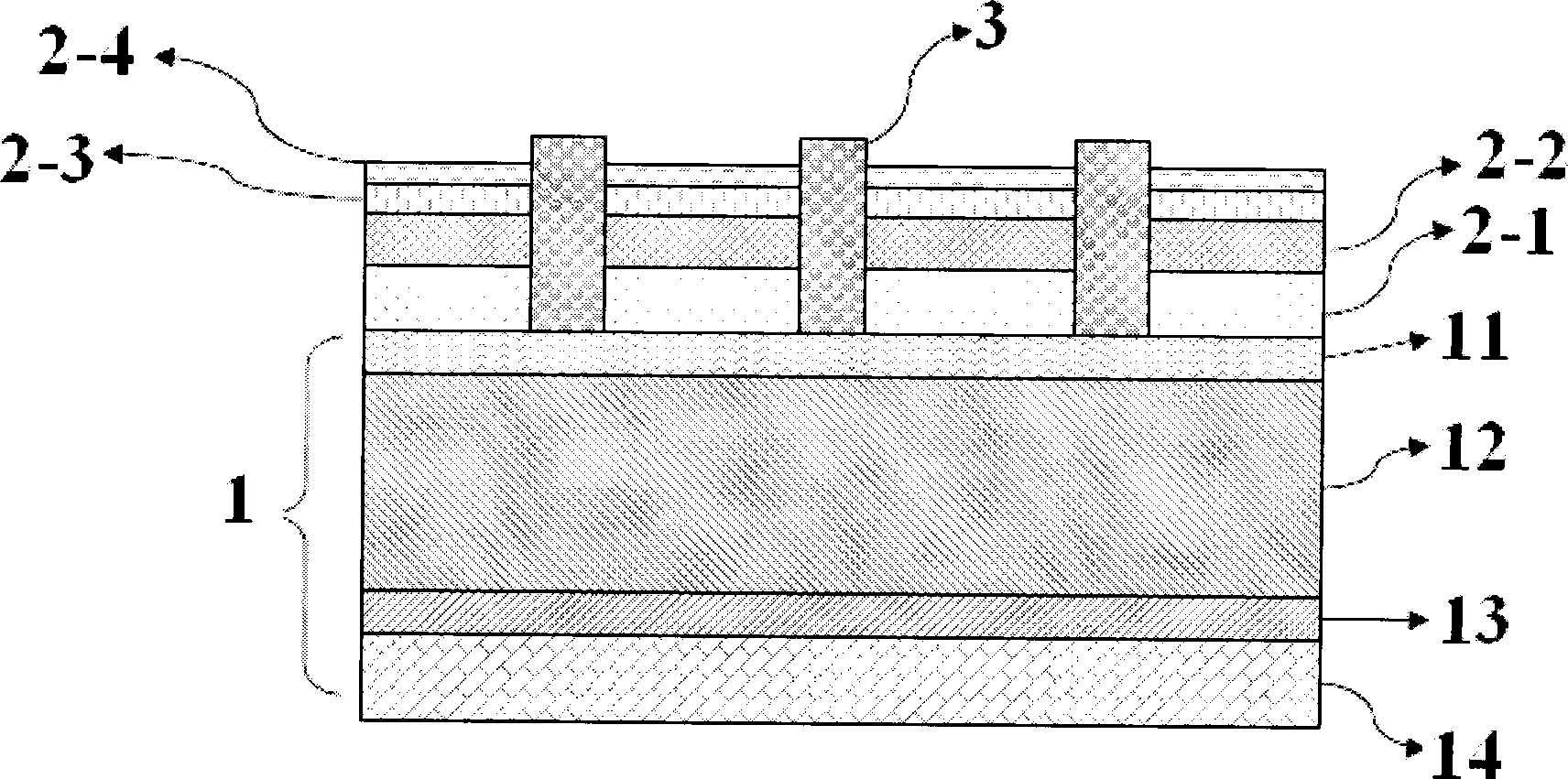
[0041] Such as figure 2 As shown, the solar cell structure of the present embodiment includes a Si battery substrate 1, and a SiNx anti-reflection passivation layer 2 is arranged on the light-facing surface of the battery substrate 1, and also includes a fired SiNx anti-reflection passivation layer 2, which is connected with the battery. Front contact electrode 3 for ohmic contact with substrate 1;
[0042] Wherein, the Si battery substrate 1 includes a P-type region 10 and an N-type region 11, and a P+ back surface field 13 and a back contact electrode 14 are formed on the back side of the Si battery substrate;
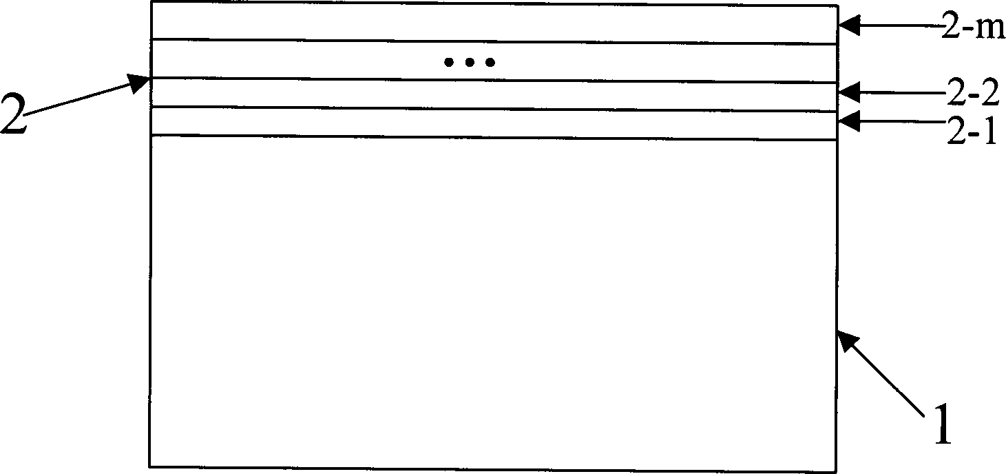
[0043] The SiNx anti-reflection passivation layer 2 includes a 4-layer film structure, along the battery substrate 1 from bottom to top are the first layer of film structure 2-1, the second layer of film structure 2-2, and the third layer of film structure 2-3 and the fourth membrane structure 2-4;
[0044] Among them, the thickness of the first film structure 2-1...
Embodiment 2
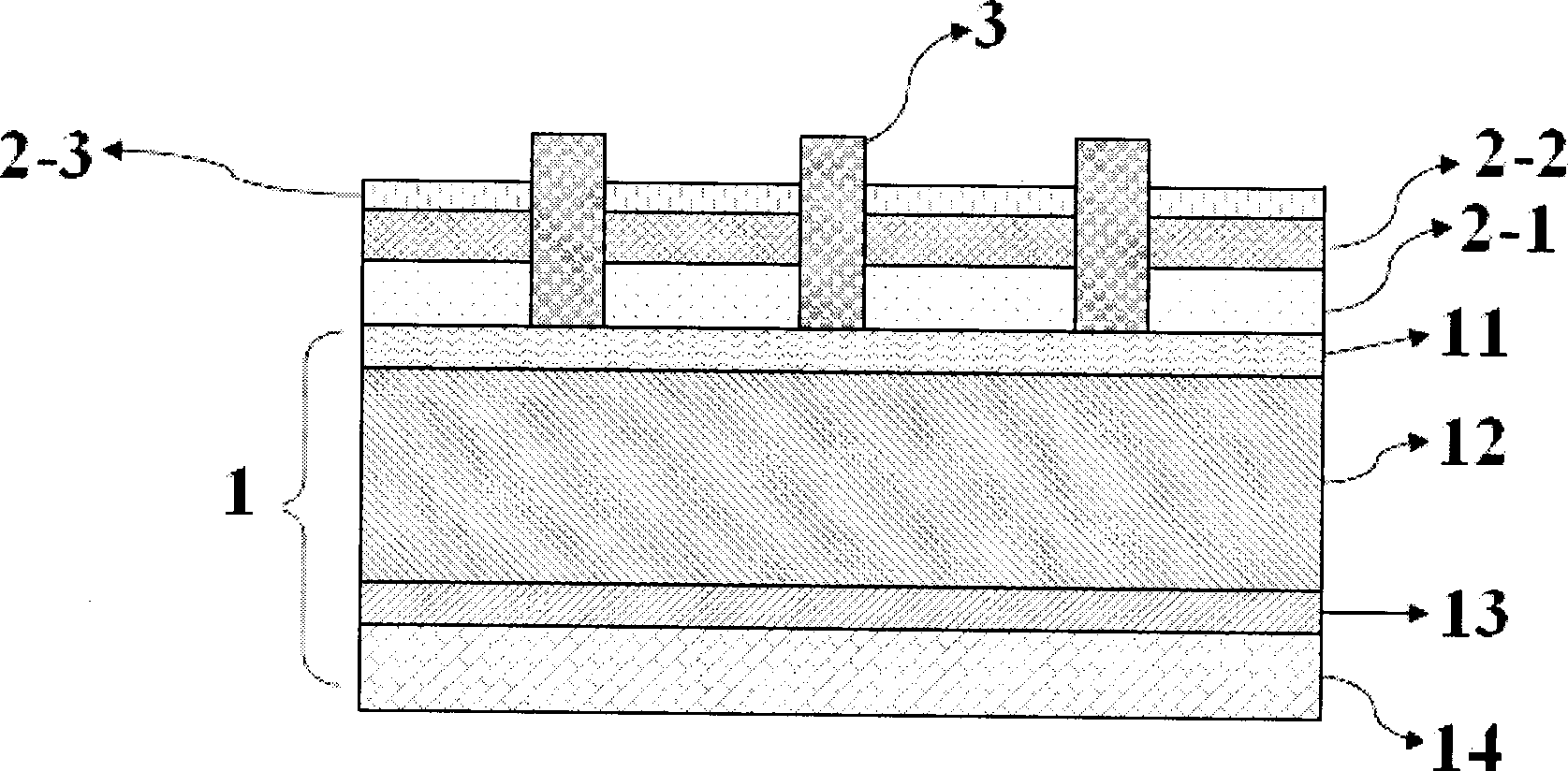
[0047] Such as image 3 As shown, the solar cell structure of the present embodiment includes a Si battery substrate 1, and a SiNx anti-reflection passivation layer 2 is arranged on the light-facing surface of the battery substrate 1, and also includes a fired SiNx anti-reflection passivation layer 2, which is connected with the battery. Front contact electrode 3 for ohmic contact with substrate 1;
[0048] Wherein, the Si battery substrate 1 includes a P-type region 10 and an N-type region 11, and a P+ back surface field 13 and a back contact electrode 14 are formed on the back side of the Si battery substrate;
[0049] The SiNx anti-reflection passivation layer 2 includes a three-layer film structure, which is the first layer film structure 2-1, the second layer film structure 2-2, and the third layer film structure 2-3 from bottom to top along the battery substrate 1. ;
[0050] Among them, the thickness of the first film structure 2-1 is about 77nm, and the refractive in...
Embodiment 3
[0073] This embodiment is a preparation method for the solar cell structure provided in Embodiment 1, as shown in Figure 5, wherein Figure 5(a) is a process flow diagram of this embodiment, and Figure 5(b) is the same as Figure 5 (a) The corresponding implementation effect diagram of the technological process, including the following steps:
[0074] S21, removing the damaged layer on the surface of the P-type silicon substrate, forming an anti-reflection surface structure and chemical cleaning.
[0075] See S21' for the implementation effect of this step.
[0076] S22, in POCl 3 The diffusion of the n-type layer is carried out in the atmosphere.
[0077] That is, an n-type layer is formed on the surface of the p-type silicon substrate, thereby producing a PN junction. The implementation effect of this step is shown in S22'.
[0078] S23, removing the peripheral PN junction.
[0079] In this step, plasma is used to etch the edge of the silicon wafer to prevent conduction on...
PUM
 Abstract
Description
Claims
Application Information
 - R&D
- Intellectual Property
- Life Sciences
- Materials
- Tech Scout
- Unparalleled Data Quality
- Higher Quality Content
- 60% Fewer Hallucinations
Browse by: Latest US Patents, China's latest patents, Technical Efficacy Thesaurus, Application Domain, Technology Topic, Popular Technical Reports.
© 2025 PatSnap. All rights reserved.Legal|Privacy policy|Modern Slavery Act Transparency Statement|Sitemap|About US| Contact US: help@patsnap.com


