
Method for removing NOx and SOx from fluid catalytic cracking (FCC) flue gas

A flue gas removal technology, applied in chemical instruments and methods, separation methods, air quality improvement, etc., can solve problems such as heat exchanger corrosion, blockage, serious corrosion problems, etc., to prevent the generation of escaped ammonia, Guaranteed denitrification efficiency and improved absorption efficiency

Active Publication Date: 2012-01-11
CHINA PETROLEUM & CHEM CORP +1
View PDF6 Cites 9 Cited by
  • Summary
  • Abstract
  • Description
  • Claims
  • Application Information

AI Technical Summary

Problems solved by technology

In this method, ammonia is required to be supplemented stoichiometrically, otherwise excessive ammonia will cause a series of problems, such as the generation of viscous NH in the heat exchanger. 4 HSO 3 , the heat exchanger will suffer from severe corrosion and clogging
In addition, (1) The setting of the heat exchanger in the process is unreasonable, without considering the serious corrosion of the equipment after the waste heat recovery of the flue gas and the cooling of the flue gas, and once the flue gas temperature fluctuates greatly, the process cannot be self-adjusted To adapt to changing working conditions; (2) The setting of the dust collector in the process is unreasonable, and the influence of dust on the life and activity of the catalyst is not considered; (3) The escape of NH 3 Secondary pollution problem caused; (4) The heat exchanger is mainly considered to remove NO x After the flue gas is cooled, the corrosion problem after cooling is not considered, and the recovery of this part of heat is not considered.

Method used


Image

  • Method for removing NOx and SOx from fluid catalytic cracking (FCC) flue gas
  • Method for removing NOx and SOx from fluid catalytic cracking (FCC) flue gas
  • Method for removing NOx and SOx from fluid catalytic cracking (FCC) flue gas

Examples


Embodiment 1

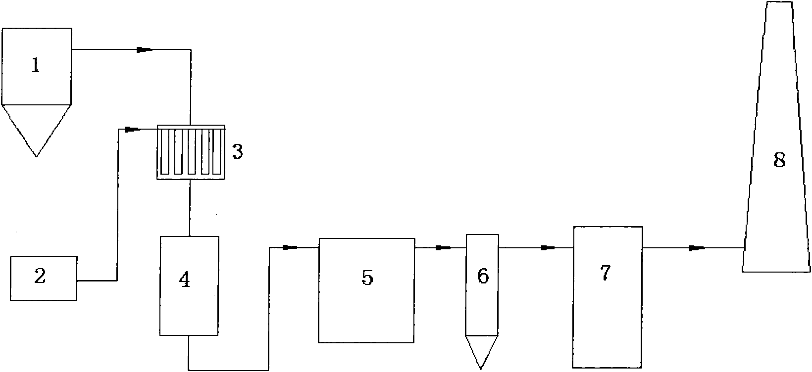
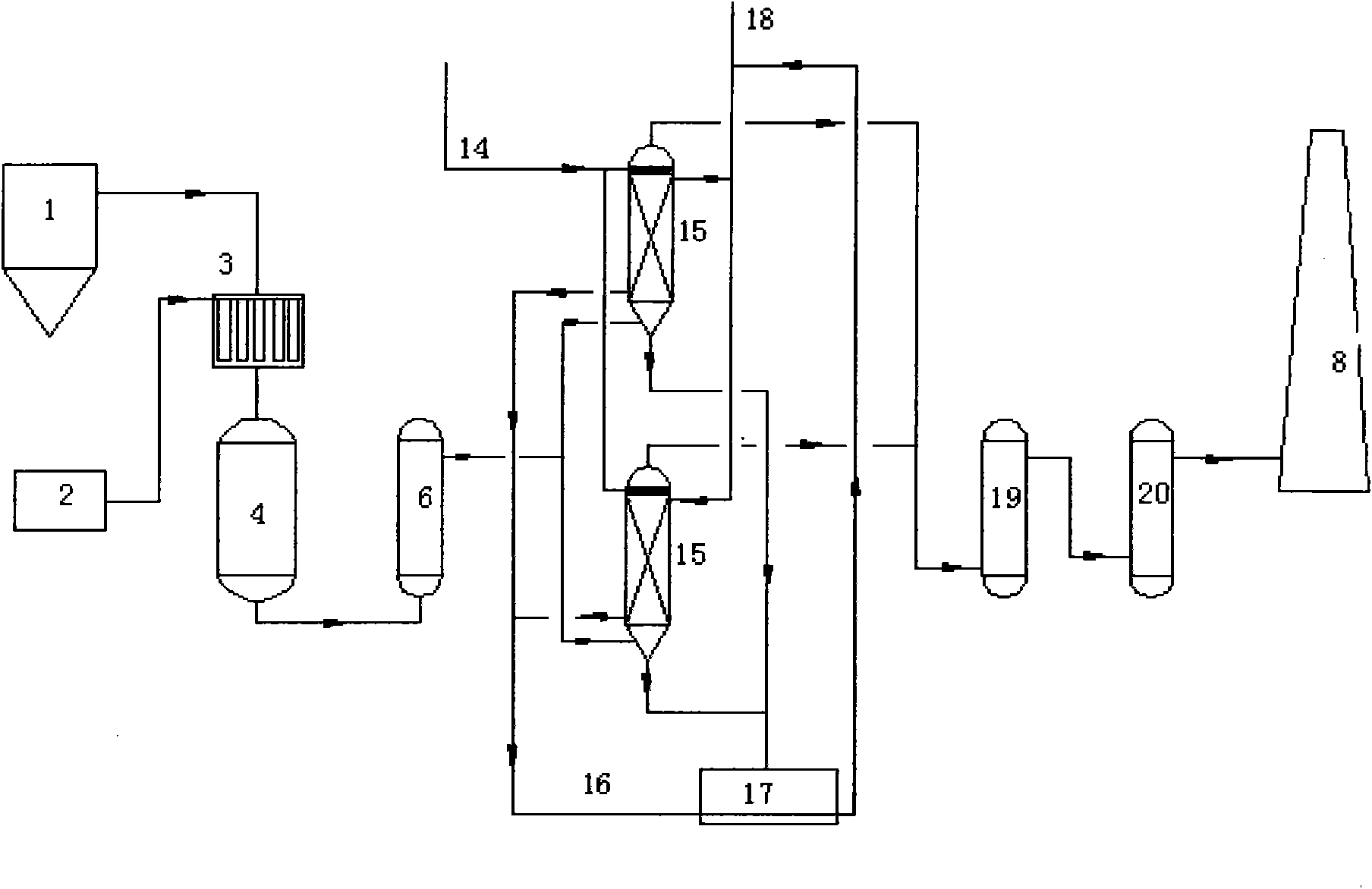
[0043] Embodiment 1 (see figure 2 )

[0044] Flue gas from FCC boiler system 1, air volume 6m 3 / h, temperature 300℃~400℃, containing 1000mg / m 3 NO x , 1000mg / m 3 SOx enters the flue gas-ammonia gas mixer 3, where the flue gas is fully and evenly mixed with the air-ammonia gas mixture from the ammonia supply unit 2, and the ammonia gas-air mixture gas volume is 0.2m 3 / h (Ammonia consumption is NO in flue gas x and SOx complete reaction required amount), after mixing with air, then enters the catalytic reduction reactor 4 downwards, the catalyst adopts the catalyst of CN200910204252.5, and this catalyst has good catalytic activity to SCR reaction.

[0045] In the catalyst bed, NO x and NH 3 N 2 and H 2 O, a soot blower is installed between the beds of the catalytic reduction reactor, and the fly ash adsorbed on the surface of the catalyst is blown back by air and then enters the dust collector to be removed. The dust collector adopts electrostatic dust removal.

[...

Embodiment 2

[0047] Embodiment 2 (see figure 2 )

[0048] Flue gas from FCC boiler system 1, air volume 30m 3 / h, temperature 300℃~400℃, containing 600mg / m 3 NO x , 2000mg / m 3 SOx enters the flue gas-ammonia gas mixer 3, where the flue gas is fully and evenly mixed with the air-ammonia gas mixture from the ammonia supply unit 2, and the ammonia-air gas mixture volume is 1m 3 / h (Ammonia consumption is NO in flue gas x and SOx complete reaction required amount), after mixing with air, then enters the catalytic reduction reactor 4 downwards, the catalyst adopts the catalyst of CN200910204252.5, and this catalyst has good catalytic activity to SCR reaction. The dust collector adopts bag dust removal, and the filter aperture is 1 to 5 mesh.

[0049] In the catalyst bed, NO x and NH 3 N 2 and H 2 O, a soot blower is installed between the beds of the catalytic reduction reactor, and the fly ash adsorbed on the surface of the catalyst is blown back by air and then enters the dust colle...

Embodiment 3

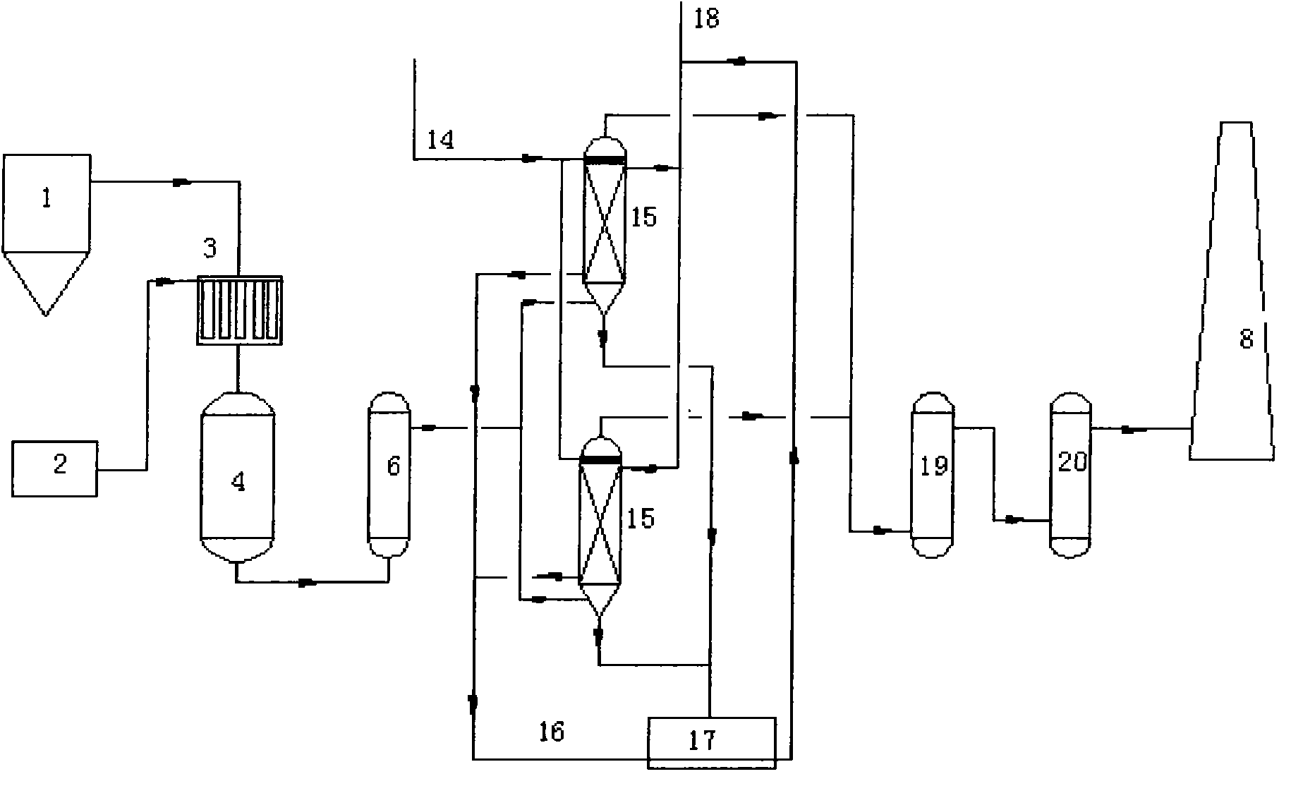
[0051] Embodiment 3 (see figure 2 )

[0052] Flue gas from FCC boiler system 1, air volume 500m 3 / h, temperature 300℃~400℃, containing 500mg / m 3 NO x , 1000mg / m 3 SOx enters the flue gas-ammonia gas mixer 3, where the flue gas is fully and evenly mixed with the air-ammonia gas mixture from the ammonia supply unit 2, and the ammonia-air gas mixture volume is 15m 3 / h (Ammonia consumption is NO in flue gas x and SOx complete reaction required amount), after mixing with air, then enters the catalytic reduction reactor 4 downwards, the catalyst adopts the catalyst of CN200910204252.5, and this catalyst has good catalytic activity to SCR reaction.

[0053] In the catalyst bed, NO x and NH 3 N 2 and H 2 O, a soot blower is installed between the beds of the catalytic reduction reactor, and the fly ash adsorbed on the surface of the catalyst is blown back by air and then enters the dust collector to be removed. The dust collector adopts bag dust removal, and the filter ape...


PUM


Abstract

The invention provides a method for removing NOx and SOx from fluid catalytic cracking (FCC) flue gas. The method comprises the following steps of: mixing FCC flue gas and ammonia, performing selective reduction reaction of NOx in the presence of a catalyst, delivering the dust removed flue gas subjected to the selective reduction reaction to ammonium salt reclaiming and washing towers, delivering the flue gas cooled in the ammonium salt reclaiming and washing towers to an alkali liquor reverse contact desulfurization tower, and then discharging the treated flue gas, wherein the number of the ammonium salt reclaiming and washing towers is at least two, and the ammonium salt reclaiming and washing towers are used for flue gas heat exchange / ammonium salt washing switching operation and have heat exchange type structures. By the method, the denitration and desulfurization processes are finished, ammonium salt is produced, energy consumption is saved, alkali consumption in the desulfurization process is saved, and the desulfurization cost is reduced.

Description

technical field [0001] The invention relates to a treatment method for FCC flue gas in an oil refinery, in particular to a denitrification and desulfurization process for the FCC flue gas in a refinery. Background technique [0002] NOx and SOx are one of the main sources of air pollution. NOx and SOx in the atmosphere mainly come from exhaust gases from industrial processes related to combustion processes and exhaust emissions from motor vehicles and ships. [0003] Nitrogen oxides are collectively referred to as NOx, and the most harmful ones are: NO, NO 2 . The main hazards of NOx are as follows: (1) toxic to the human body; (2) toxic to plants; (3) can form acid rain and acid fog; (4) form photochemical smog with hydrocarbons; (5) destroy the ozone layer . [0004] In the atmosphere, SO 2 It will be oxidized to form sulfuric acid mist or sulfate aerosol, which is an important precursor of environmental acidification. The concentration of sulfur dioxide in the atmos...

Claims


Application Information

Patent Timeline
IPC IPC(8): B01D53/90B01D53/78B01D53/60
CPCY02A50/20
Inventor 李勇
Owner CHINA PETROLEUM & CHEM CORP
Learn More