Polysilicon ingot casting method with low defect and high output and thermal field structure thereof

A polysilicon, low-defect technology, applied in the growth of polycrystalline materials, chemical instruments and methods, crystal growth, etc., can solve the problems of high grain boundary and dislocation defect density, low solar cell efficiency, and insignificant cost advantages. Improve crystal quality, reduce energy consumption, and facilitate the effect of adjusting the crystal growth interface

Active Publication Date: 2012-01-25
TRINA SOLAR CO LTD
View PDF3 Cites 26 Cited by
  • Summary
  • Abstract
  • Description
  • Claims
  • Application Information

AI Technical Summary

Problems solved by technology

The high energy consumption is mainly due to the position of the heater in the upper half of the entire thermal field structure. The heater is located on the top and upper side of the thermal field. In order to maintain the temperature gradient of crystal growth, more energy is lost.
At present, the 450kg polycrystalline ingot furnace type is generally used in the industry. Due to the problem of production capacity or the load of the slicer, the actual feeding amount is generally 390-420kg. With the development of the industry, the competition is becoming more and more fierce, and the solar cell manufacturers are getting more and more More and more attention is paid to cost control. In order to increase production capacity and reduce energy costs, various new equipment are constantly being developed. The polycrystalline furnace has a larger furnace type (800kg) successfully developed, and these large furnace types are developing horizontally. , that is, the original 450kg polycrystalline ingot furnace type can cut 25 small pieces of 156mm×156mm×250mm, and the 800kg

Method used


Image

  • Polysilicon ingot casting method with low defect and high output and thermal field structure thereof
  • Polysilicon ingot casting method with low defect and high output and thermal field structure thereof
  • Polysilicon ingot casting method with low defect and high output and thermal field structure thereof

Examples


Embodiment 1

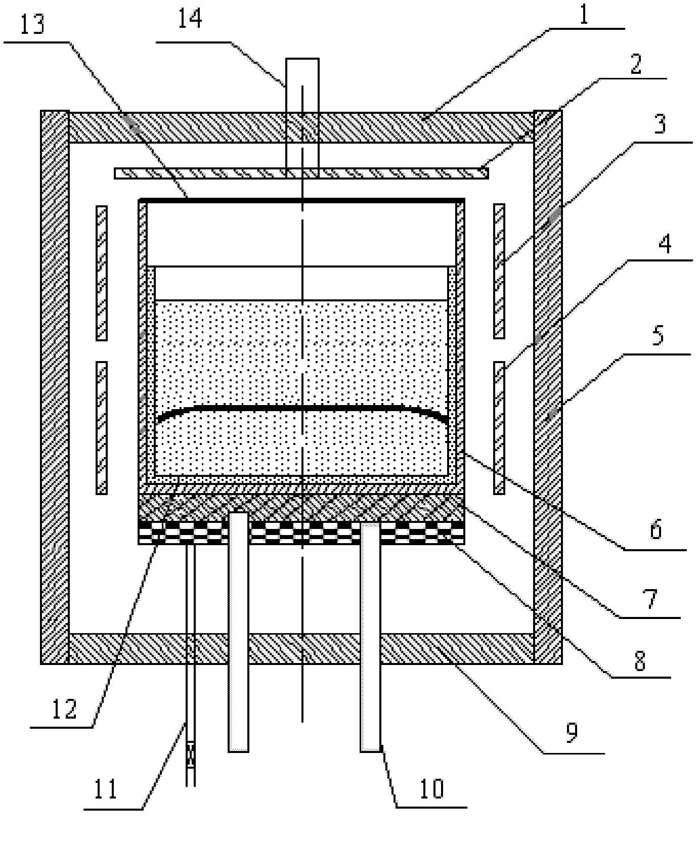
[0025] After the quartz crucible 12 is filled with 650kg of silicon material, the outsourcing graphite crucible 6 is placed on the support block 7, the side wall 5 of the insulation cover and the lower insulation plate 9 are closed, and the distance between the top heater 2 and the support block 7 reaches 650mm. The furnace body is evacuated, and after the vacuum degree required by the process is reached, the top heater 2, the side heater 3 and the side heater 4 start to work. After initial preheating, the inert protective gas argon is gradually introduced through the protective gas introduction pipe 14, The pressure in the furnace is maintained at 0.5 atm. Due to the heat preservation effect of the heat preservation cover, the temperature in the heat preservation cover can be raised to a high temperature of about 1500°C, so that the silicon material can be heated and melted within more than ten hours. The argon gas that circulates during the materialization can carry the impur...

Embodiment 2

[0030] After the quartz crucible 12 is filled with 750kg of silicon material, the outsourcing graphite crucible 6 is placed on the support block 7, the side wall of the heat preservation cover 5 and the lower insulation plate 9 are closed, and the distance between the top heater 2 and the support block 7 reaches 700mm. The furnace body is evacuated, and after the vacuum degree required by the process is reached, the top heater 2, the side heater 3 and the side heater 4 start to work. After initial preheating, the inert protective gas argon is gradually introduced through the protective gas introduction pipe 14, The pressure in the furnace is maintained at 0.6atm. Due to the heat preservation effect of the heat preservation cover, the temperature in the heat preservation cover can be raised to a high temperature of about 1500°C, so that the silicon material can be heated and melted within more than ten hours. The argon gas that circulates during the materialization can carry the...

Embodiment 3

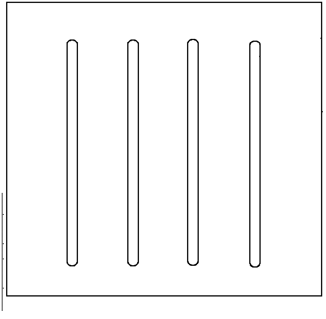
[0035] Quartz crucible 12 first lays a strip-shaped crystal-oriented single crystal with a certain thickness at the position corresponding to the cooling point of the support block at the bottom of the crucible, and then fills it with 650kg of silicon material, outsources the graphite crucible 6, and places it on the support block 7, and the support block 7 With 4 strip cooling spots, such as image 3 , the insulation cover side wall 5 and the lower insulation board 9 are closed, the distance between the top heater 2 and the support block 7 reaches 650mm, the furnace body is evacuated, and after reaching the vacuum degree required by the process, the top heater 2 and the side heater 3 and side lower heater 4 start to work, and after the initial preheating, the inert protective gas argon is gradually introduced through the protective gas introduction pipe 14 to maintain the pressure in the furnace at 0.4 atm. After rising to a high temperature of 1400°C, lift the heat preserva...


PUM


Abstract

The invention relates to a polysilicon ingot casting method with low defect and high output and a thermal field structure thereof. The thermal field structure comprises a thermal insulation cover system, a crucible system, split resistance heaters, a support part and a cooling device, wherein the three heaters are independently and separably controlled to lower energy consumption to the maximum degree and bring convenience for regulating a crystal growth interface, thereby obtaining an evener crystal growth interface, improving crystal quality and solving the later-stage cooling problem of the crystal growth because of the increase of the height of the ingot casting. A support block with the unique design and a cooling device are combined to realize the purpose of local cooling, so that the local position on the bottom of a crucible generates cold spots at the early stage of the crystal growth; nucleation is carried out firstly to reduce nucleation spots, and lateral temperature gradient is obtained to provide the necessary condition for the lateral growth of the crystal nucleus; crystalline grains are enlarged to reduce a crystal boundary to the large extent; and microdefects, such as dislocation and the like, are lowered.

Description

technical field [0001] The invention belongs to the technical field of solar cell ingot casting, and relates to a low-defect high-yield polycrystalline silicon ingot casting method and a thermal field structure thereof. Background technique [0002] In the field of solar photovoltaics, the method of directional solidification to produce polysilicon ingots is a commonly used method. The basic principle is: place the polysilicon raw material in a quartz ceramic crucible, place it in a specific thermal field system, and heat it until it is completely melted; The bottom of the crucible begins to cool, and the silicon solution begins to crystallize at the bottom of the crucible and gradually grows (solidifies); The consumption is around 3800 degrees. The high energy consumption is mainly due to the fact that the heater is located in the upper half of the entire thermal field structure. The heater is located at the top and upper side of the thermal field. In order to maintain the...

Claims


Application Information

Patent Timeline
IPC IPC(8): C30B28/06C30B29/06
Inventor 陈雪
Owner TRINA SOLAR CO LTD
Why Eureka
Try Eureka