Solar maximum power point tracking system and method for implementing same

A technology of maximum power point and tracking system, applied in control/regulation systems, photovoltaic power generation, instruments, etc., can solve problems such as poor control accuracy, poor adaptability, and complex algorithms

Active Publication Date: 2013-07-03
TIANJIN HUIGAO MAGNETICS
View PDF5 Cites 0 Cited by
  • Summary
  • Abstract
  • Description
  • Claims
  • Application Information

AI Technical Summary

Problems solved by technology

The various methods mentioned above have their own advantages and disadvantages in practical applications. For example, the constant voltage control method has simple control and good stability, but poor control accuracy and poor adaptability; while the fuzzy control method has high control accuracy and excellent dynamic and steady-state performance. Good, but the algorithm is complicated, requires a complex CPU controller, and the cost and power consumption of the system itself increase
So far there is no ideal solar cell maximum power point tracking technology

Method used


Image

  • Solar maximum power point tracking system and method for implementing same
  • Solar maximum power point tracking system and method for implementing same
  • Solar maximum power point tracking system and method for implementing same

Examples


Embodiment 1

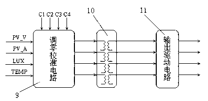
[0061] like figure 1 The solar maximum power point tracking system shown integrates each unit circuit, and designs a system circuit board with the switch circuit 2, the zero adjustment circuit 9 and the isolation circuit 10 as off-chip components, in which: the front-end state detection circuit 1 There are four analog signal input terminals, which are respectively connected with the external solar cell voltage sensor, solar cell current sensor, external temperature sensor and external light intensity sensor; the digital control signal terminal is connected with a group of digital control signal terminals of the controller 3; The four analog signal output terminals are connected to the input terminals of the front-end signal conditioning circuit 8; the front-end state detection circuit 1 works under the control of the controller 3 to complete the detection of the current state of the solar battery voltage, current, temperature and light intensity signals.

[0062] There are fo...

Embodiment 2

[0071] The realization of the solar maximum power point tracking system of the present invention passes through the following steps successively:

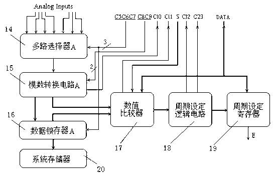
[0072] First, after the system is powered on, the controller 3 sets an initial value for the internal step setting register 27 of the disturbance step generator 6 and the internal cycle setting register 19 of the disturbance cycle generator 7 through the data bus DATA; The limit protection value of the signal is written in the 16-unit data latch 37 of the value comparator 17 .

[0073] Second, the controller 3 sends control information, starts the back-end state detection circuit 4 to test the current value of the load voltage, current and load circuit temperature, and filters and normalizes the collected signals.

[0074] The 3rd, the numerical value comparator 17 inside disturbance cycle generator 7 compares the data collected with the data prestored in 16 unit data latches 37, if any data exceeds the protection limit value, th...

Embodiment 3

[0083] The solar battery maximum power point tracking workflow of the solar battery maximum power point tracking system of the present invention is as follows:

[0084] The structure of the solar battery maximum power point tracking system with variable period variable step size disturbance is as follows: figure 1 As shown, the stable working process of the system is as follows:

[0085] In the first step, the front-end state detection circuit 1 and the back-end state detection circuit 4 will cyclically collect the solar cell voltage, solar cell current, solar cell temperature, solar radiation intensity, load DC bus voltage, load DC bus current and load circuit temperature .

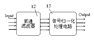
[0086] In the second step, the front-end signal conditioning circuit 8 and the back-end signal conditioning circuit 5 respectively perform low-pass filtering and signal normalization processing on the seven analog signals, and the low-pass filter filters out high-frequency interference of 50 Hz and ab...


PUM


Abstract

The invention relates to a solar maximum power point tracking system and a method for implementing the same. A system circuit consists of a front-end state detection circuit, a switching circuit, a controller, a rear-end state detection circuit, a rear-end signal conditioning circuit, a disturbance step-length generator, a disturbance cycle generator and a front-end signal conditioning circuit. By adoption of a control method for variable-cycle and variable-step-length disturbance, the controller, a data acquisition circuit and a logic control circuit can be designed into an integrated circuit. The solar maximum power point tracking system is implemented by using high-efficiency simple control software. The invention has the characteristics of simple circuit structure, simple software algorithm, low power consumption, high efficiency and the like; and the power consumption of the own power supply of the system can be reduced. By the invention, the control method for the maximum power point tracking and load tracking of a solar battery is realized, and load protection can be provided. The invention is particularly applicable to some small and medium-sized solar storage battery charging circuits and solar battery power stations which independently operate.

Description

technical field [0001] The present invention relates to the technical field of photovoltaic power generation, in particular to a solar maximum power point tracking system and its implementation method. The system has the function of tracking the maximum power point of solar cells by performing disturbance observation with variable cycle and variable step length, and can simplify the solar power generation system. Hardware and software overhead, reducing dynamic power consumption of power conversion circuits, can be used in solar cell independent power generation systems, grid-connected power generation systems, etc. Background technique [0002] Solar energy is a clean and pollution-free huge energy source, and the maximum development and utilization of solar energy will be an important direction for the development of human science and technology; due to the global energy crisis and the urgency of environmental protection, and the warning of major nuclear accidents in the ...

Claims


Application Information

Patent Timeline
Patent Type & Authority Patents(China)
IPC IPC(8): G05F1/67H02N6/00
CPCY02E10/58Y02E10/56
Inventor 周锎耿卫东杜学伟郑海华吕前进
Owner TIANJIN HUIGAO MAGNETICS
Why Eureka
Try Eureka