
Structure of surface mount device micro electromechanical oscillator and manufacturing method thereof

An electric oscillator and surface-attached technology, which is applied to the structure of a surface-attached micro-electromechanical oscillator and its manufacturing field, can solve the problems of increasing manufacturing costs, stopping vibration, and consuming large amounts of power, thereby reducing production costs, improving production efficiency, The effect of reducing equipment expenditure

Inactive Publication Date: 2012-01-25
郭启勋
View PDF3 Cites 0 Cited by
  • Summary
  • Abstract
  • Description
  • Claims
  • Application Information

AI Technical Summary

Problems solved by technology

[0005] The current manufacturing method of SMD quartz oscillator is to use a single ceramic base with a metal upper cover, or both the base and the upper cover are made of ceramic materials to complete the quartz oscillator sub-package operation, which consumes a lot of power when packaging. Soldering is carried out, and because the coefficient of thermal expansion (Coefficient of thermal expansion, CTE) of the material of the base and the upper cover is different, it is easy to cause poor airtightness of the negative pressure chamber after the packaging is completed, and the oscillator works unstable or stops oscillating; and the oscillator is integrated with the When the circuit is integrated, because the material of the oscillator base and the upper cover is not the same as that of the integrated circuit, it increases the difficulty of integration. In addition, if it needs to be directly inserted into the integrated circuit, an additional machine needs to be added, so an additional manufacturing cost
[0006] It can be seen that the above-mentioned existing manufacturing technology still has many deficiencies, is not a good designer, and needs to be improved urgently.

Method used


Image

  • Structure of surface mount device micro electromechanical oscillator and manufacturing method thereof
  • Structure of surface mount device micro electromechanical oscillator and manufacturing method thereof
  • Structure of surface mount device micro electromechanical oscillator and manufacturing method thereof

Examples


Embodiment Construction

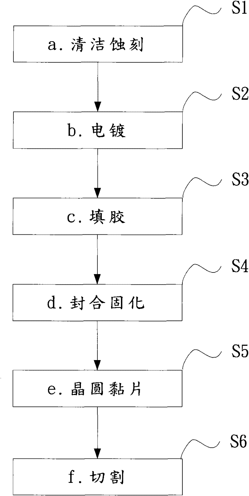
[0053] see figure 1 , figure 1 It is a flow chart of the manufacturing method of the surface-mounted micro-electro-mechanical oscillator. The manufacturing method of the surface-mounted micro-electromechanical oscillator of the present invention includes the following steps: a. Cleaning and etching S1; b. Electroplating S2; c. Glue filling S3; d. Sealing and curing S4; e. wafer bonding S5; f. cutting S6; the steps will be described in more detail below:

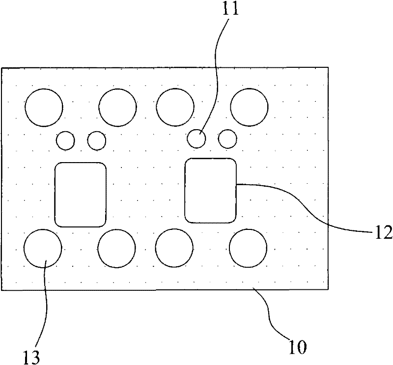
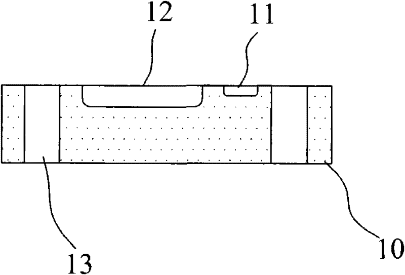
[0054] a. Clean etch S1, see also Figure 2A and Figure 2B , Figure 2A Complete front view for etch of glass wafer substrate base, Figure 2B The side view of the etching of the glass wafer substrate base is completed. As shown in the figure, the photoresist (Coating Photoresist) is etched on the cleaned glass wafer base base 10 of 3 to 8 inches or more and several diameters are etched. A hole 13 of about 100um to 150um, a plurality of fixed grooves 11 with a diameter of about 10um and a depth of about 3 to 5um, and a ...


PUM


Abstract

The invention relates to a manufacturing method of a surface mount device micro electromechanical oscillator and a structure thereof. According to the invention, there are following advantages: 1, batch manufacture of the surface mount device micro electromechanical oscillator is realized in a micro electromechanical mode; 2, the oscillator can be completely integrated with an integrated circuit element; 3, the oscillator integrated with other electronic crystal grains can be packaged into a same integrated circuit, so that a usage quantity of a single electronic element can be effectively reduced and manufacturing costs can be substantially reduced; 4, a production precision of a design on a special gluing area is improved, thereby reducing occurrences of glue-spilling or empty glue situations and reducing an unqualified rate.

Description

technical field [0001] The invention relates to a structure and a manufacturing method of a surface mount (Surface Mount Device, SMD) microelectromechanical (Micro ElectroMechanical Systems, MEMS) oscillator, especially suitable for improving manufacturing efficiency, and can be combined with a microprocessor controller (Microprocessor control unit , MCU) grain (Die) integrated packaging to reduce the use of external components in product design, and simplify the technical field of electronic product manufacturing processes. Background technique [0002] With the advancement of science and technology, as long as timing signals are required, or products used to stabilize the frequency of radio transmitters, oscillators are required as their signal sources, such as televisions (TVs), radios (Radios), personal computers (PCs), printers ( Printer), Network Interface Card, Bluetooth Products, Mobile Phone, etc. [0003] The types of oscillators mainly include RC oscillators, RLC...

Claims


Application Information

Patent Timeline
Patent Type & Authority Applications(China)
IPC IPC(8): H03H3/02B81C1/00B81B3/00H03H9/19
Inventor 郭启勋
Owner 郭启勋
Learn More