Process for removing acid gas from flue gas by using residual heat of flue gas

An acid gas and flue gas technology, applied in gas treatment, climate sustainability, greenhouse gas capture, etc., which can solve the problems of wasting latent heat and not meeting energy saving

Inactive Publication Date: 2012-02-08
NANJING UNIV
View PDF2 Cites 33 Cited by
  • Summary
  • Abstract
  • Description
  • Claims
  • Application Information

AI Technical Summary

Problems solved by technology

However, the flue gas discharged from coal-fired power plants contains a certain amount of waste heat, and the direct discharge wastes a huge amount of latent heat, which does not meet the requirements of energy saving.

Method used


Image

  • Process for removing acid gas from flue gas by using residual heat of flue gas
  • Process for removing acid gas from flue gas by using residual heat of flue gas

Examples


Embodiment 1

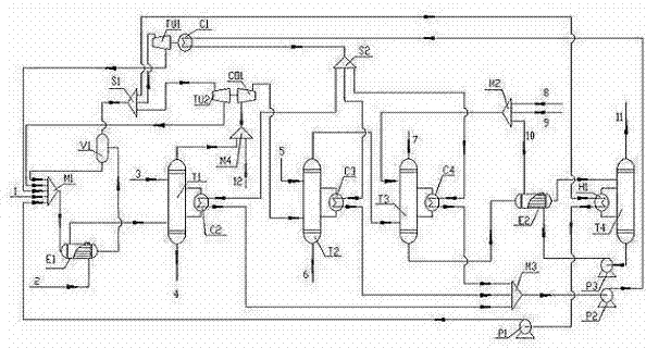
[0025] Now deal with the flue gas, in terms of volume fraction, it contains CO 2 is 13.98%, O 2 3.49%, N 2 72.87%, SO 2 0.21%, H 2 O is 9.45%, and the flue gas volume is 1,124,980 m 3 / h, the flue gas temperature is 300°C. It can be seen from the above content that since it does not contain nitrogen oxides and contains SO 2 and CO 2 Acid gas, need desulfurization absorption tower T1 and CO 2 Absorption tower T3 and CO 2 The regeneration tower T4 does not need the denitrification absorption tower T2. The flue gas enters the heat exchanger E1 through the pipeline 2, so that the temperature of the flue gas is reduced from 300°C to 120°C, and the water is heated at the same time, and the mixture of water vapor and liquid water obtained enters the phase separator V1, and the water returns after phase separation Heat exchanger E1 recirculates. The steam is divided into two streams through the splitter S1, one stream is used as a heating source, and the steam is converted i...

Embodiment 2

[0027] Now deal with the flue gas, in terms of volume fraction, it contains CO 2 7.6%, O 2 10%, N 2 54%, H 2 O is 28%, containing SO per cubic meter 3 Mass 1500 mg, containing NO X Mainly NO, 1200 mg, flue gas volume 12000 m 3 / h, the flue gas temperature is 300°C. It can be seen from the above content that due to the nitrogen oxides, SO 2 and CO 2 Acid gas, need desulfurization absorption tower T1, denitrification tower to absorb T2, CO 2 Absorption tower T3 and CO 2 Regeneration tower T4. First pass the flue gas through the heat exchanger E1, so that the temperature of the flue gas is reduced from 300°C to 120°C, and at the same time, the water from the pipeline 1 through the mixer M1 is heated after passing through the heat exchanger E1, and the heated water and steam The mixture enters the phase separator V1, and the liquid water after phase separation returns to the heat exchanger E1 through the mixer M1 for recycling. After the phase separation, the water vapo...

Embodiment 3

[0030] Now deal with the flue gas, in terms of volume fraction, it contains CO 2 is 12.06%, O 2 10.1%, N 2 60.54%, SO 2 0.12%, NOx 0.1%, H 2 O is 17.08%, and the flue gas volume is 1,442,650 m 3 / h, the flue gas temperature is 415°C. It can be seen from the above content that due to the nitrogen oxides, SO 2 and CO 2 For acidic gas, desulfurization absorption tower T1, denitrification absorption tower T2, CO 2 Absorption tower T3 and CO 2 Regeneration tower T4. First pass the flue gas through the heat exchanger IE1, so that the temperature of the flue gas is reduced from 415 ° C to 120 ° C, and at the same time, the water from the pipeline 1 through the mixer M1 is heated after passing through the heat exchanger E1, and the heated water and steam The mixture enters the phase separator V1, and the liquid water after phase separation returns to the heat exchanger IE1 for recycling through the mixer M1. After the phase separation, the water vapor is divided into three s...


PUM


Abstract

The invention discloses a process for removing acid gas from flue gas by using residual heat of the flue gas. The process comprises the following steps of: introducing flue gas into a heat exchanger I; lowering the temperature of the flue gas; making the flue gas enter a desulfurizing-absorbing tower; heating and gasifying water in the tube pass of the heat exchanger and making the heated and gasified water enter a phase splitter; combining the heat exchanger and the phase splitter into a waste heat boiler, wherein the generated steam pressure is 3-6 Pa; partitioning the water steam into three streams for entering a low-pressure steam turbine I, a low-pressure steam turbine II and a heater respectively; driving the low-pressure steam turbine I with the water steam for supplying a power source to a refrigerator to obtain chilled water, wherein the chilled water is taken as cooling media of the desulfurizing-absorbing tower, a denitrifing-absorbing tower and CO2 absorbing tower respectively to keep the temperatures of the towers at respective needed temperatures; driving the low-pressure steam turbine II with the second stream of water steam; compressing desulfurized flue gas; making the desulfurized flue gas enter the denitrifing-absorbing tower to remove NOx and generate dilute nitric acid simultaneously; and supplying a heat source to a CO2 regeneration tower through a heater H1 by using the third stream of water steam to regenerate a CO2 absorption liquid, using the water steam circularly, and generating and collecting CO2 simultaneously.

Description

technical field [0001] The invention relates to a technology for removing acid gas from flue gas by using its waste heat. Background technique [0002] my country is one of the few countries in the world where coal is the main energy source, and it is the largest producer and consumer of coal in the world. Coal still accounts for a large proportion of my country's energy structure, and my country's coal-based energy consumption structure is the most important reason for my country's increasingly serious air pollution. According to statistics, 90% of sulfur dioxide, 67% of nitrogen oxides, and 70% of soot emissions in my country come from coal combustion. Among them, coal-fired power stations, coal-fired industrial boilers, coal-fired furnaces and other flue gas pollution problems are the most prominent. Taking the 10-year period from 2001 to 2010 as a sample, coal power accounts for about 75% of China's annual power generation. With the accelerated pace of industrializati...

Claims


Application Information

Patent Timeline
Patent Type & Authority Applications(China)
IPC IPC(8): B01D53/75B01D53/18B01D53/50B01D53/56B01D53/62
CPCY02C10/04B01D2257/504B01D53/62B01D53/18B01D2258/0283B01D53/56B01D53/50B01D53/1475B01D2259/65B01D53/78Y02C20/10B01D53/75Y02A50/20Y02C20/40
Inventor 张志炳周政钱红亮吴平铿
Owner NANJING UNIV
Why Eureka
Try Eureka