

Tunneling field effect transistor (TFET) and manufacturing method thereof
A tunneling field effect and transistor technology, which is applied in semiconductor/solid-state device manufacturing, semiconductor devices, electrical components, etc., can solve the problems of limiting the application of TFET devices, small on-state current, etc., achieve good sub-threshold characteristics, and simple preparation process Effect
- Summary
- Abstract
- Description
- Claims
- Application Information
AI Technical Summary
Problems solved by technology
Method used
Image

Examples
Embodiment Construction
[0034] The present invention will be further described below by example. It should be noted that the purpose of the disclosed embodiments is to help further understand the present invention, but those skilled in the art can understand that various replacements and modifications are possible without departing from the spirit and scope of the present invention and the appended claims of. Therefore, the present invention should not be limited to the content disclosed in the embodiments, and the protection scope of the present invention is subject to the scope defined in the claims.
[0035] A specific example of the preparation method of the present invention includes Figure 1 to Figure 4b Process steps shown:
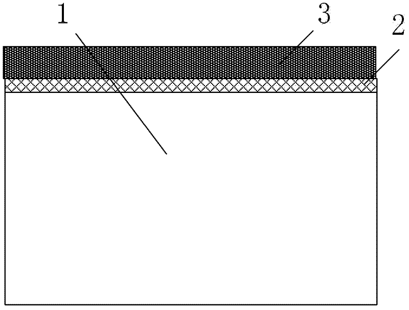
[0036] 1. Fabricate an active region isolation layer on a bulk silicon wafer silicon substrate 1 with a crystal orientation of (100) using shallow trench isolation technology, and the doping concentration of the substrate is lightly doped; then thermally grow a gate di...
PUM
 Abstract
Description
Claims
Application Information