Double workpiece stage rotary exchange device based on synchronous gear direction adjustment

A technology of double workpiece table and synchronous gear, which is applied in the direction of photolithography exposure device, microlithography exposure equipment, etc., can solve the problems of shortening the balance time, small moment of inertia, loss of laser interferometer target, etc., and achieves improved photolithography The effect of improving machine productivity, improving operating efficiency, and shortening the balance time

Inactive Publication Date: 2014-02-05
HARBIN INST OF TECH
View PDF13 Cites 0 Cited by
  • Summary
  • Abstract
  • Description
  • Claims
  • Application Information

AI Technical Summary

Problems solved by technology

In the present invention, the double-table rotation is switched to three beats, and the workpiece table does not spin during the table-changing process, which solves the problems of phase inversion of the workpiece table, cable entanglement, laser interferometer target loss, etc.
At the same time, the present invention adopts the platform changing method that the workpiece table rotates around the center of the abutment, avoids rotating the whole abutment, and solves the problems of large radius of gyration and large moment of inertia in the prior art, and the moment of inertia is small. Shorter times improve workbench operating efficiency and lithography machine productivity
The present invention also solves the problems of large impact torque and many beats in the existing linear channel change scheme, and can adopt a smaller mass balance system, which is beneficial to shorten the balance time, simplify the system at the same time, reduce costs, and shorten the cycle time of channel change. It takes less time to change the platform, which can effectively improve the productivity of the lithography machine

Method used


Image

  • Double workpiece stage rotary exchange device based on synchronous gear direction adjustment
  • Double workpiece stage rotary exchange device based on synchronous gear direction adjustment
  • Double workpiece stage rotary exchange device based on synchronous gear direction adjustment

Examples


Embodiment Construction

[0021] Below in conjunction with accompanying drawing, the present invention is described in further detail:

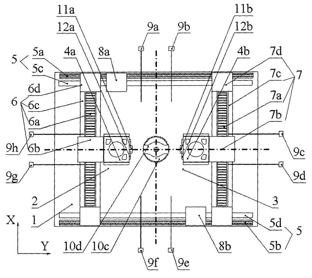
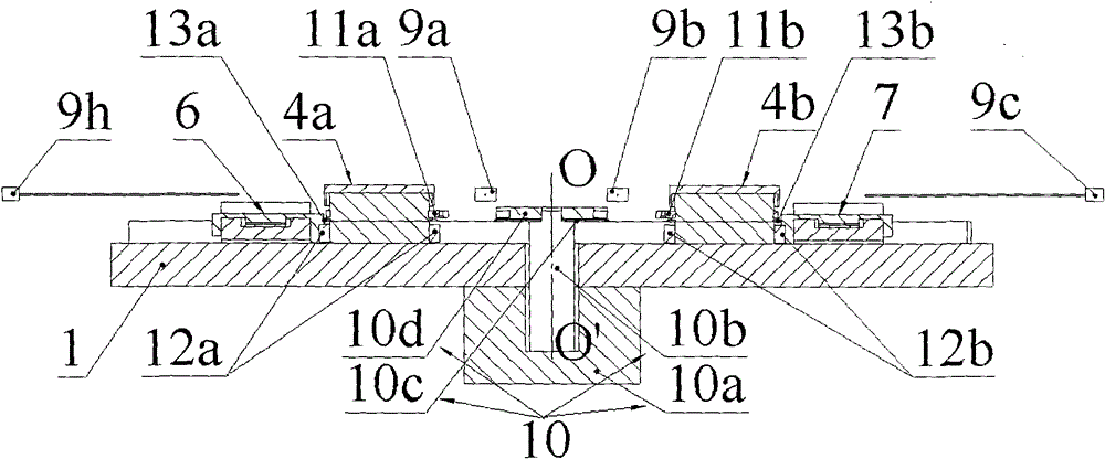
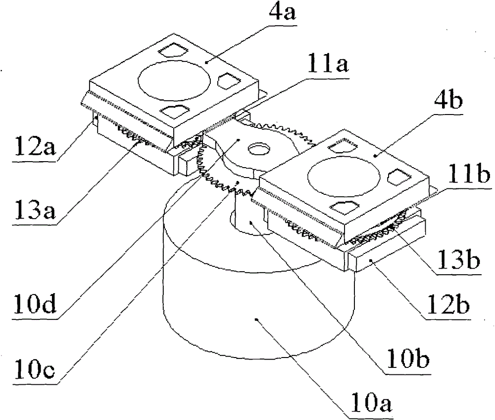
[0022] A dual-workpiece rotary exchange device based on synchronous gear direction adjustment. The exposure station 2 and the pretreatment station 3 are set at both ends of the base 1 in the Y direction, and the Y positions are respectively set along the long sides of the base 1. To the long-stroke linear motion unit 5, the X-direction first long-stroke linear motion unit 6 and the X-direction second long-stroke linear motion unit 7 are respectively arranged on the exposure station 2 and the pretreatment station 3, and the first workpiece table 4a and The second workpiece table 4b is detachably fitted on the X-direction first long-stroke linear motion unit 6 and the X-direction second long-stroke linear motion unit 7, and the X-direction first long-stroke linear motion unit 6 and the X-direction second long-stroke linear motion unit The long-stroke linear motion unit ...


PUM


Abstract

A double workpiece stage rotary exchange device based on synchronous gear direction adjustment belongs to semiconductor manufacturing equipment; the device comprises a rotary stage-exchange device composed of a rotating motor stator, a rotating motor mover, a rotary stage-exchange gear, and a rotating connecting member; a workpiece stage rotating ring sleeve and a workpiece stage gear are disposed at the waist part of a workpiece stage; a workpiece connecting device is disposed at the side surface; after the rotary stage-exchange device is docked with the workpiece connecting device, the workpiece stage is driven to rotate around a base stage center so as to realize position exchange; during the three-beat rotary stage exchange process of the invention, the workpiece stage does not spin, which solves the problems of workpiece stage phase reversal, cable winding, and laser interferometer object loss in current rotary stage exchange modes; meanwhile the invention adopts a stage exchange mode in which the workpiece stage rotates around a base stage center, which avoids the rotation of the whole base stage, provides less rotary inertia and shorter stage exchange time under a condition with a same torque, and increases the operation efficiency of the workpiece stage and the yield of a lithography machine.

Description

technical field [0001] The invention belongs to the technical field of semiconductor manufacturing equipment, and mainly relates to a double-workpiece rotary exchange device based on synchronous gear direction adjustment. Background technique [0002] Lithography machine is one of the important ultra-precision equipment in the manufacture of very large scale integrated circuits. The resolution and engraving accuracy of the lithography machine determine the minimum line width of the integrated circuit chip. At the same time, the yield of the lithography machine greatly affects the production cost of the integrated circuit chip. As the key subsystem of the lithography machine, the workpiece table It also determines the resolution, overlay accuracy and productivity of the lithography machine to a large extent. [0003] Productivity is one of the main goals of lithography machine development. Under the condition of satisfying the resolution and overlay accuracy, improving the ...

Claims


Application Information

Patent Timeline
Patent Type & Authority Patents(China)
IPC IPC(8): G03F7/20
Inventor 谭久彬杨远源王雷
Owner HARBIN INST OF TECH
Why Eureka
Try Eureka