Spiral luminous tube pin bending machine

A technology of bending machine and lamp tube, which is used in glass re-molding, glass manufacturing equipment, glass molding and other directions, can solve the problems of incapable of streamlined production, inability to compare, difficult to explain, etc., and achieves inflation time and pressure. Accurate control, high pass rate and high work efficiency

Inactive Publication Date: 2012-04-11
杭州森浦设备制造有限公司
View PDF4 Cites 3 Cited by
  • Summary
  • Abstract
  • Description
  • Claims
  • Application Information

AI Technical Summary

Problems solved by technology

CN102030463 discloses the patented technology of "Spiral Tube Bending Machine" of Zhongshan Shengqian Machinery Equipment Co., Ltd. The lamp clamping mechanism of the bending mechanism, the bending actuator, and the flame heating system are all installed on a rectangular workbench On the top, there is no turntable, there is only one station, it cannot be streamlined production, and the work efficiency is low
Recently, I learned from legends that someone has applied for a patent for a multi-station spiral lamp tube bending machine that uses a turntable as a workbench and can perform streamlined operations. There must also be a station mechanism, a clamping mechanism, a bending mechanism, and a steering mechanism. , the existence of the fire head heating mechanism, but what is certain is that the specific structure of these mechanisms should be different for different designers, each with its own characteristics, each has its own advantages, because it has not been made public, it is impossible to compare, which is better. It’s hard to say clearly, after they are released to the public, we will compare and evaluate them

Method used


Image

  • Spiral luminous tube pin bending machine
  • Spiral luminous tube pin bending machine
  • Spiral luminous tube pin bending machine

Examples


Embodiment Construction

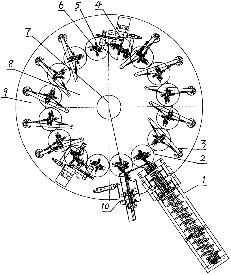
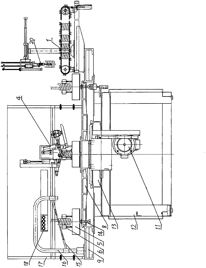
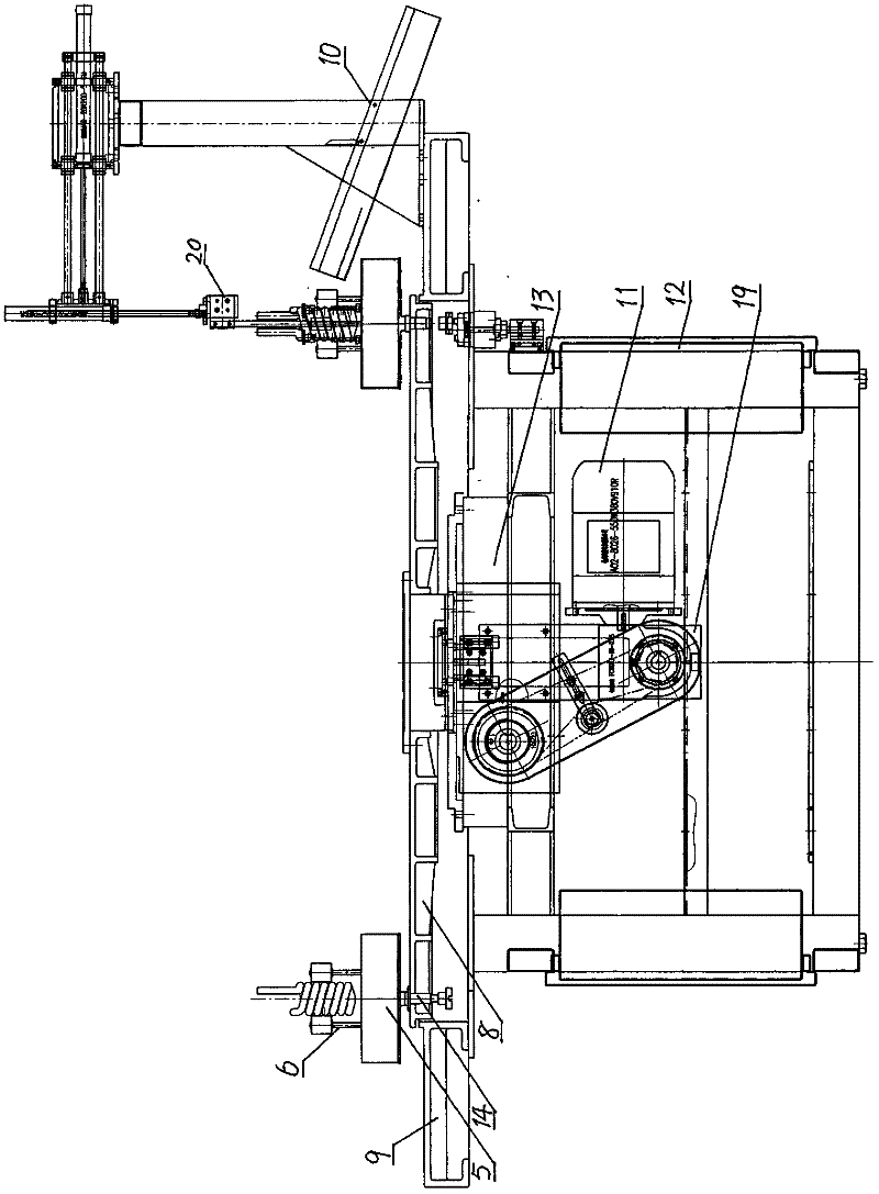
[0028] The present invention is described in detail below in conjunction with embodiment and with reference to accompanying drawing: see Figure 1-3 , is a structural schematic diagram of sixteen stations as an example. Spiral lamp tube bending machine, including distribution box, automatic control system, motor 11, gear reducer, cylinder, workbench and frame 12, motor 11, gear reducer 19, divider 13 and ring workbench 9 are installed on On the frame 12, a turntable 8 is installed on the central rotating shaft 7, and an annular workbench 9 is arranged around the turntable 8, and the surface of the turntable 8 near the outer circumference is equidistantly installed with sixteen to twenty-four stations 2, now press There are 16 stations and the station 2 adjacent to the inner side of the delivery tube setting device 1 is used as the first station, that is, the starting station, and the counterclockwise order is as follows: the second to sixth stations all have fire head heating ...


PUM


Abstract

The invention relates to a spiral luminous tube pin bending machine which comprises a distribution box, an automatic control system, a motor, a reduction gear box and a workbench, wherein a central rotating shaft (8) is provided with a rotary table (8) which is provided with 16-24 equally spaced stations (2); in the case of 16 stations, the station close to the inner side of a tube conveying and placing device (1) is called the primary station (2), and other stations in counterclockwise sequence comprise the 2-6th and 9-13th stations provided with a fire head heating device (3), the 7th and 14th stations provided with a pin bending device (4), the 8th station the lower part of which is provided with a station steering device (14), the 15th station which is a natural cooling station, and the 16th station provided with a tube unloading device (10) nearby; and a spiral luminous tube with V-shaped pins is subjected to each of the process steps on the 16 stations, so that the V-shaped pins are bent into straight pins. The pin bending machine has the advantages of automate line production, low energy consumption, high work efficiency, labor saving and capability of improving high-temperature working environment. In addition, the machine is capable of collecting afterheat for preheating and thermal insulation of the luminous tube to be processed, and has the advantages of reasonable inflation time and pressure control, stable product quality and high qualification rate.

Description

technical field [0001] The invention relates to a machine for bending the splayed leg of a spiral energy-saving lamp tube into a straight leg. Background technique [0002] Due to factors such as miniaturization, energy saving, and good lighting effects, electronic energy-saving lamp tubes are produced by many manufacturers and their application range is increasing. During the bending process of the spiral lamp tube in the energy-saving lamp tube, due to the limitation of processing equipment and technology, after a straight glass tube is bent into a spiral body, the two ends of the glass tube are often in a figure-eight shape. Left on one end of the helix, commonly known as the splayed foot, such a spiral tube has not been coated with phosphor, nor installed with a stem, tungsten wire and mercury pellets, and is commonly called an open tube in the industry. The existence of the splayed feet makes it impossible to insert the two legs into high-temperature resistant plastic ...

Claims


Application Information

Patent Timeline
Patent Type & Authority Applications(China)
IPC IPC(8): C03B23/045
Inventor 李建明韩跃富
Owner 杭州森浦设备制造有限公司
Why Eureka
Try Eureka