
Thermochemical vapor deposition reactor and method for improving thermal radiance in reactor

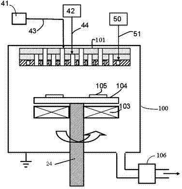
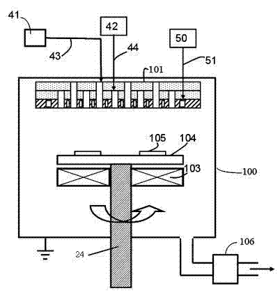
A technology of vapor phase deposition and thermal radiation rate, which is applied in the direction of gaseous chemical plating, metal material coating process, coating, etc., can solve the problem of affecting the thermal field distribution of the reaction chamber, the increase of the thermal radiation rate of the device, and the deviation of the processing effect from the ideal value, etc. Problems, to ensure the uniformity and effect, improve the effect of heat radiation rate

Active Publication Date: 2012-04-11
ADVANCED MICRO FAB EQUIP INC CHINA +1
View PDF6 Cites 6 Cited by
  • Summary
  • Abstract
  • Description
  • Claims
  • Application Information

AI Technical Summary

Problems solved by technology

[0004] During the above-mentioned high-temperature chemical reaction process of epitaxial growth, the temperature in the MOCVD reaction chamber is very high, usually reaching about 1200°C. Some devices installed in the reaction chamber, such as: heating resistance wire molybdenum Mo and stainless steel on the inner wall of the reaction chamber ( stainless steel), these devices have a polished metal surface. With the long-term reaction, the originally bright device surface will accumulate some deposits, or the surface material will be oxidized. These reasons will cause the heat radiation rate of the device to increase. For example, the reaction The thermal radiation rate of the inner wall of the cavity was originally less than 0.1, but it became greater than 0.7 after a long time. The thermal radiation rate of the Mo heating resistance wire was originally 0.05, but it became greater than 0.2 after long-term operation. The change of the rate will affect the thermal field distribution in the reaction chamber. As time goes by, the processing effect will deviate from the ideal value more and more

Method used


Image

  • Thermochemical vapor deposition reactor and method for improving thermal radiance in reactor
  • Thermochemical vapor deposition reactor and method for improving thermal radiance in reactor

Examples


Embodiment 1

[0021] The surface preparation method includes the following steps:

[0022] Step 1, the device is oxidized;

[0023] Step 2, coating the soluble salt of the refractory metal on the surface of the device;

[0024] Step 3. Reduction of salts and oxides to metal form.

Embodiment 2

[0026] The surface preparation method includes the following steps:

[0027] Step 1, the device is oxidized;

[0028] Step 2, coating the surface of the device with alumina;

[0029] Step 3, heating the device;

[0030] Step 4, coating the soluble salt of the refractory metal on the surface of the device;

[0031] Step 5. Reduction of the salt to the metal form.

Embodiment 3

[0033] The surface preparation method includes the following steps:

[0034] Step 1. Heat the device at a temperature of 725°C for 5 minutes in an air atmosphere;

[0035] Step 2, coating the surface of the device with alumina;

[0036] Step 3, in H 2 Heat the device at 1650°C for 5 minutes in the atmosphere;

[0037] Step 4, immerse the device in ammonium tungstate solution;

[0038] Step 5, in H 2 The device was heated at 1000° C. for 10 minutes in the atmosphere.


PUM


Abstract

The invention discloses a thermochemical vapor deposition reactor and a method for improving the thermal radiance in the reactor. Before a reaction, a device in a reaction cavity is subjected to surface pretreatment, so as to change the roughness of the surface of the device or the material composition on the surface of the device to passivate the surface of the device, thereby improving the thermal radiance value of the device. According to the invention, the surface of the device in the reaction cavity can reach stable thermal radiance before a reaction, thereby ensuring processing uniformity and effect.

Description

technical field [0001] The invention relates to a thermal chemical vapor deposition reactor for producing compound semiconductor optoelectronic devices and a method for increasing the heat radiation rate in the reactor. Background technique [0002] Thermal chemical vapor deposition reactors, especially metal organic chemical vapor deposition systems (hereinafter referred to as MOCVD) are the core equipment for the production of semiconductor optoelectronic devices. In the metal organic chemical vapor deposition (MOCVD) process, the reaction gas is introduced into the reaction chamber from the gas source, so that the epitaxial wafer placed in the reaction chamber grows epitaxially to form a lattice structure film. [0003] Emissivity represents the ability of the surface of an object to radiate heat at a certain temperature (a coefficient between 0 and 1), called the thermal emissivity, usually the brighter the material (such as polished silver), the higher the thermal emiss...

Claims


Application Information

Patent Timeline
Patent Type & Authority Applications(China)
IPC IPC(8): C23C16/46
Inventor 杜志游
Owner ADVANCED MICRO FAB EQUIP INC CHINA
Learn More