Tertiary treatment device of automobile exhaust and separation method thereof

A treatment device and a three-stage treatment technology, applied in the field of air pollution control, can solve problems such as low efficiency, and achieve the effects of simple structure, reduced emissions, and reduced costs

Inactive Publication Date: 2012-05-02
NORTH CHINA ELECTRIC POWER UNIV (BAODING)
View PDF7 Cites 34 Cited by
  • Summary
  • Abstract
  • Description
  • Claims
  • Application Information

AI Technical Summary

Problems solved by technology

[0008] The present invention aims at the deficiency that the efficiency of the existing methods for removing harmful gases in

Method used


Image

  • Tertiary treatment device of automobile exhaust and separation method thereof
  • Tertiary treatment device of automobile exhaust and separation method thereof
  • Tertiary treatment device of automobile exhaust and separation method thereof

Examples


Embodiment 1

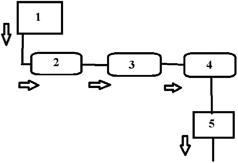
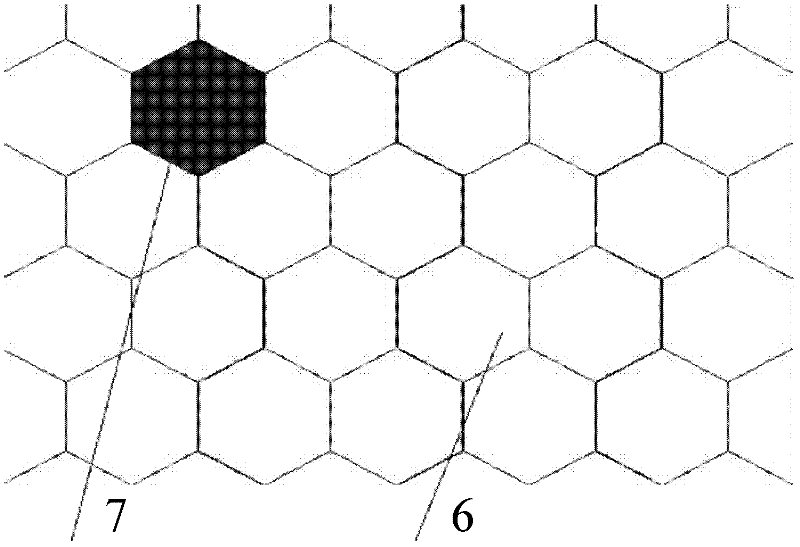
[0021] Such as figure 1 , 2 As shown, a three-stage treatment device for automobile exhaust gas is composed of a three-way catalytic converter 1, a primary primary treatment device 2, a secondary sulfur oxide nitrogen oxide treatment device 3 and a third-stage carbon dioxide treatment device 4. Wherein, the first-level primary treatment device 2 is a primary separator, and the primary separator is a honeycomb carrier structure 6 filled with activated carbon particles 7 (such as image 3 ), the honeycomb carrier and activated carbon particles form an adsorption layer for rough treatment of automobile exhaust. The secondary sulfur oxide nitrogen oxide treatment device 3 is mainly composed of photocatalytic reactors (including TiO 2Photocatalytic reaction layer 11 and ultraviolet lamp 12) consist of fan 9, pre-filter layer 10, TiO 2 Photocatalytic reaction layer 11, ultraviolet lamp 12, gas-oxygen mixing chamber 13, oxygen generator 14, anion generator 16 and other structures,...


PUM


Abstract

The invention discloses a tertiary treatment device of automobile exhaust and a separation method thereof, belonging to the technical field of atmospheric pollution treatment. The treatment device is composed of a ternary catalytic converter, a primary initial treatment device, a secondary sulfur oxide and nitrogen oxide treatment device and a tertiary carbon dioxide treatment device, wherein the primary initial treatment device is a primary separator which is internally filled with activated carbon particles; the secondary sulfur oxide and nitrogen oxide treatment device mainly comprises a photocatalysis reactor which is internally filled with titanium dioxide; the tertiary carbon dioxide treatment device is a carbon dioxide separator which is internally filled with activated carbon fiber; and the ternary catalytic converter, the primary initial treatment device, the secondary sulfur oxide and nitrogen oxide treatment device and the tertiary carbon dioxide treatment device are sequentially connected in series. After the automobile exhaust passes through the tertiary treatment device, the exhaust separation treatment can be realized, and the emission of harmful gas is reduced from the source.

Description

technical field [0001] The invention belongs to the technical field of air pollution control, and in particular relates to a three-stage separation device for automobile tail gas and a separation method thereof. Background technique [0002] In the 21st century, automobile pollution has increasingly become a global problem. As the number of automobiles increases and the scope of use becomes wider and wider, its negative effects on the world's environment are also increasing, especially harmful to the urban environment, causing respiratory diseases, causing excessively high levels of ozone in the surface air, and aggravating urban pollution. The heat island effect aggravates the deterioration of the urban environment. According to relevant expert statistics, by the beginning of the 21st century, the tail gas emitted by automobiles accounted for 30-60% of air pollution. With the increase of motor vehicles, the tail gas pollution is becoming more and more serious, changing fr...

Claims


Application Information

Patent Timeline
IPC IPC(8): F01N3/035B01D53/94B01D53/60B01D53/62
CPCY02C10/04Y02T10/22Y02A50/20Y02C20/40Y02T10/12
Inventor 赵珊黄国和张晓东安春江魏佳姚尧李晟阳艾利
Owner NORTH CHINA ELECTRIC POWER UNIV (BAODING)
Why Eureka
Try Eureka