Uncooled infrared detector

An infrared detector and non-cooling technology, applied in the field of infrared thermal imaging, can solve the problems of increasing process flow and process steps, and achieve the effect of large optical fill factor

Inactive Publication Date: 2012-05-02
UNIV OF ELECTRONICS SCI & TECH OF CHINA
View PDF3 Cites 13 Cited by
  • Summary
  • Abstract
  • Description
  • Claims
  • Application Information

AI Technical Summary

Problems solved by technology

The double-layer structure can better improve the duty cycle of the detection unit, but both need to make double sacrificial layers, which significantly increases ...

Method used


Image

  • Uncooled infrared detector
  • Uncooled infrared detector
  • Uncooled infrared detector

Examples


Embodiment 1

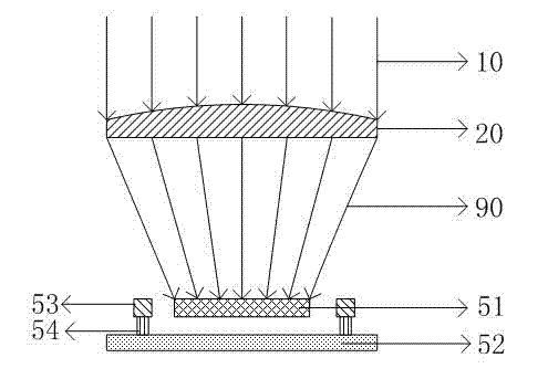
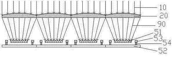
[0027] see Figure 2~Figure 3 , the infrared window 20 of the present invention is a microlens array structure with light converging effect, preferably a microlens array structure with light converging effect composed of microconvex lens units, which is directly processed by infrared window material germanium sheet, that is, directly The surface of the germanium sheet is processed into a regularly arranged microlens array structure; the processing steps are: patterning the germanium sheet by ordinary photolithography, and then corroding the germanium sheet with a mixed solution of hydrogen peroxide and sodium hydroxide. Due to the lateral corrosion, the cross-section of the figure presents an inclined slope, forming a microlens shape. After the etching is completed, the glue is removed and cleaned to form an infrared window 20 with a simple microlens structure on the surface.

[0028] The size of the microlens on the infrared window is consistent with the size of the detection...

Embodiment 2

[0033] like Figure 4 As shown, the infrared window 20 is a microlens array structure, and the units of the microlens array are composed of a substrate 21 and a microconvex lens unit film or a Fresnel lens unit film 22 of the surface microlens array structure. The substrate material is a germanium sheet, and then a ZnS film is prepared on the surface. The ZnS thin film is made into the shape of a microlens array through the methods of glue coating, photolithography, development and corrosion, and the lens array can converge the incident infrared light. In this way, an infrared window 20 with a microlens array structure is formed. The rest of the structure and manufacturing steps are the same as in Embodiment 1.

[0034] The infrared window 20 of the present invention is made of infrared-transmitting materials such as Ge, silicon, ZnSe, ZnS, GaAs, GaP, diamond, sapphire, MgF4, spinel single crystal or polycrystal, or is made of an infrared-transmitting polymer material. The ...


PUM


Abstract

The invention discloses an uncooled infrared detector comprising an infrared window and a detection image element array which is provided with a micro-bridge unit structure, wherein the infrared window is a micro-lens array composed of a plurality of micro convex lens units or Fresnel lens units; and a space between the micro-lens array and the detection image element array is set within a range, in which incident infrared rays can be collected on a deck of the micro-bridge unit structure of the detection image element array. The infrared window disclosed by the invention is provided with a micro convex lens array or a Fresnel lens array structure, so that lights can be collected on the deck of the detection image element array after passing through the infrared window; the structure has larger optical filling factors, so as to provide strong supports to design and preparation of detection units with smaller sizes and high flexibility of the detector; and compared with a double-layer micro-bridge unit structure, the preparation process of the detection unit is not increased.

Description

technical field [0001] The invention relates to the technical field of infrared thermal imaging, in particular to an uncooled infrared detector with a micro-convex lens array structure. Background technique [0002] Night vision technology is a technology that uses the radiation of the sky at night to illuminate the target, or uses the thermal radiation of the scenery on the earth's surface to observe the image of the scenery beyond the visible light band with the help of scientific instruments. Its core technology is sensor technology. Known methods include active and passive infrared imaging, synthetic aperture radar, millimeter-wave radar, etc. Currently, night vision imaging equipment mainly includes thermal imaging and low-light imaging equipment. [0003] Infrared thermal imaging technology is to detect the infrared rays radiated by each part of the scene itself, and use the difference in the radiation of each part of the scene itself to obtain the details of the image...

Claims


Application Information

Patent Timeline
IPC IPC(8): G01J5/02G01J5/10
Inventor 王军蒋亚东吴志明简祺霞俞磊
Owner UNIV OF ELECTRONICS SCI & TECH OF CHINA
Why Eureka
Try Eureka