Self-supporting thin polymer film

A polymer film, self-supporting technology, applied in membranes, membrane technology, semi-permeable membrane separation and other directions, can solve the problems of low density, wide size distribution, practical use limitations, etc., to achieve the effect of large surface area and high strength

Inactive Publication Date: 2012-05-02
TOKYO INST OF TECH
View PDF3 Cites 42 Cited by
  • Summary
  • Abstract
  • Description
  • Claims
  • Application Information

AI Technical Summary

Problems solved by technology

However, because the size distribution of the pores of the permeable membranes used in the past is wide and usually low density, its practical use is limited.

Method used


Image

  • Self-supporting thin polymer film
  • Self-supporting thin polymer film
  • Self-supporting thin polymer film

Examples


Embodiment 1

[0123] Block copolymers were synthesized as follows.

[0124] Liquid crystalline methacrylate monomer MA(Stb) was synthesized as follows.

[0125] 4-Butylbenzoic acid (manufactured by Tokyo Chemical Industry Co., Ltd., special grade) was reduced with boron trifluoride diethyl ether complex and sodium borohydride to obtain 4-butylbenzyl alcohol. Using the Williamson method, 4-hydroxybenzaldehyde (manufactured by Tokyo Chemical Industry Co., Ltd., special grade) and 11-bromo-1-undecanol (manufactured by Wako Pure Chemical Industries, Ltd., special grade) were condensed to obtain 4-(11- hydroxyundecyloxy)benzaldehyde. The resulting 4-butylbenzyl alcohol was brominated with hydrogen bromide, and then reacted with triphenylphosphine (manufactured by Wako Pure Chemical Industries, Ltd., special grade) to obtain (4-butylbenzyl)triphenylphosphine. Phenyl bromide obtained by making The salt reacts with potassium tert-butoxide to form salt (ylide), and then add 4-(11-hydroxyunde...

Embodiment 2

[0132] A 1% by weight solution of cellulose acetate (Mw. 30000) in acetone was spin-coated on a silicon wafer at a speed of 3000 rpm for 60 seconds to form a sacrificial layer. The film was heated at 60° C. for about 1 hour in the air to remove acetone remaining in the film. Next, a 4% by weight chloroform solution of the copolymer produced in Example 1 was spin-coated on the sacrificial layer at a speed of 2000 rpm for 30 seconds, and heat treatment (annealing treatment) was performed at 190° C. for 2 hours under vacuum, thereby A microphase-separated structure membrane is obtained.

Embodiment 3

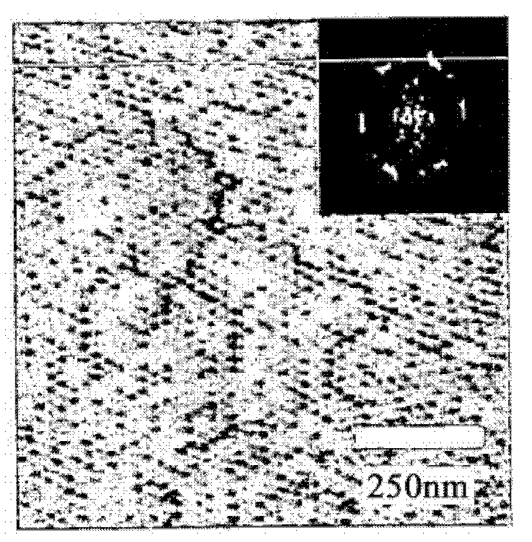
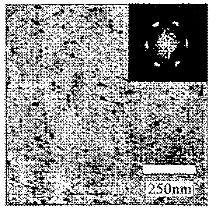
[0134] Regarding the microphase-separated structure of the polymer thin film obtained in Example 2, the surface structure was observed using an atomic force microscope (AFM). Photographs representing AFM results as figure 1 shown. Depend on figure 1 It was found that on the surface of the polymer film obtained in Example 2, a hexagonal dot pattern derived from polyethylene oxide blocks (hydrophilic polymer components) was observed.

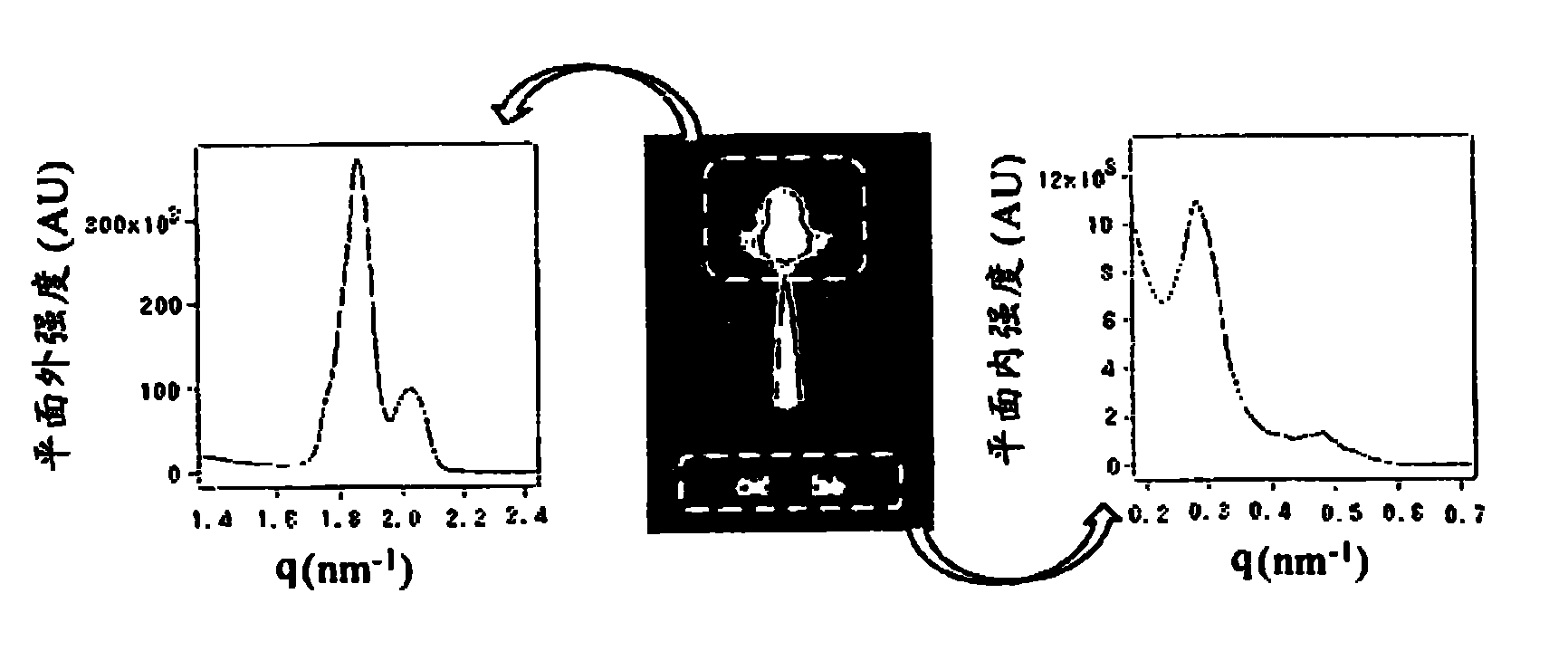
[0135] Next, the structural periodicity of the polymer film obtained in Example 2 was measured by grazing incidence small-angle X-ray scattering (GI-SAXS). The result is as figure 2 shown. Depend on figure 2 It can be seen that the polyethylene oxide block (hydrophilic polymer component) pillars in the polymer film obtained in Example 2 form a hexagonal arrangement. From the results of AFM and GI-SAXS, it can be confirmed that the polymer film obtained in Example 2 also formed a microphase-separated structure on the polyacetic acid cellulo...


PUM

PropertyMeasurementUnit
diameteraaaaaaaaaa
diameteraaaaaaaaaa
wavelengthaaaaaaaaaa

Abstract

Provided are a self-supporting thin polymer film which has a large surface area, high strength, and perpendicularly oriented cylinder structures, and a process for producing the film. The self-supporting thin polymer film is obtained from a block copolymer comprising a hydrophilic polymer component and a hydrophobic polymer component having a crosslinkable structure and bonded to the hydrophilic polymer component by covalent bonding. The self-supporting thin polymer film has cylinders therein which are constituted of the hydrophilic polymer component oriented in a certain direction, the hydrophobic polymer component having been crosslinked. The self-supporting thin polymer film has no physical pores but enables a substance to pass selectively through the cylinder parts, and can be used as various permeable films, ultrafiltration membranes, nanoreactors, and the like.

Description

technical field [0001] The present invention relates to a self-supporting polymer film and a method for manufacturing the self-supporting polymer film. More specifically, the present invention relates to a self-supporting polymer film with a vertically oriented column structure and a method for manufacturing the film. Background technique [0002] In recent years, self-supporting thin films with large surface area and nanoscale thickness have attracted attention for applications such as permselective membranes, microsensors, and drug delivery membranes. For such thin films, it has been reported that the layer-by-layer method (LbL lamination method) (Non-Patent Document 1), the Langmuir Blodgett method (LB method) (Non-Patent Document 2) and the spin coating method (Non-Patent Document 2) can be used. Document 3) is manufactured by such a method. The above method is a method of providing a sacrificial layer on a solid substrate, forming a target film on the sacrificial layer...

Claims


Application Information

Patent Timeline
Patent Type & Authority Applications(China)
IPC IPC(8): C08J5/18C08F20/26
CPCB01D67/00C08F293/00B01D2323/00C08F293/005B01D2323/30B01D2323/345B01D71/80B01D2325/02B01D67/0006C08J5/18C08F220/26C08F20/26B01D71/52C08F2220/286B01D69/125B01D71/48C08F220/286C08F220/302
Inventor 弥田智一山本崇史浅冈定幸泉谷佑
Owner TOKYO INST OF TECH
Why Eureka
Try Eureka