Fiber electrode and fiber cell, and method for producing same, facility for producing fiber electrode and fiber cell

A fiber electrode and manufacturing method technology, applied in the direction of electrolyte battery manufacturing, electrode manufacturing, secondary battery manufacturing, etc., can solve the problem that the battery structure cannot achieve high output, etc., to achieve ultra-fast charging, increase charging speed and discharge speed , The effect of reducing the internal resistance

Inactive Publication Date: 2012-05-23
KAWASAKI HEAVY IND LTD +1
View PDF13 Cites 13 Cited by
  • Summary
  • Abstract
  • Description
  • Claims
  • Application Information

AI Technical Summary

Problems solved by technology

The specific electrode thickness is not disclosed in Patent Document 2, but since the positive electrode and the negative electrode each form a rope-shaped battery, the battery structure of Patent Document 2 cannot achieve high output

Method used


Image

  • Fiber electrode and fiber cell, and method for producing same, facility for producing fiber electrode and fiber cell
  • Fiber electrode and fiber cell, and method for producing same, facility for producing fiber electrode and fiber cell
  • Fiber electrode and fiber cell, and method for producing same, facility for producing fiber electrode and fiber cell

Examples


Embodiment

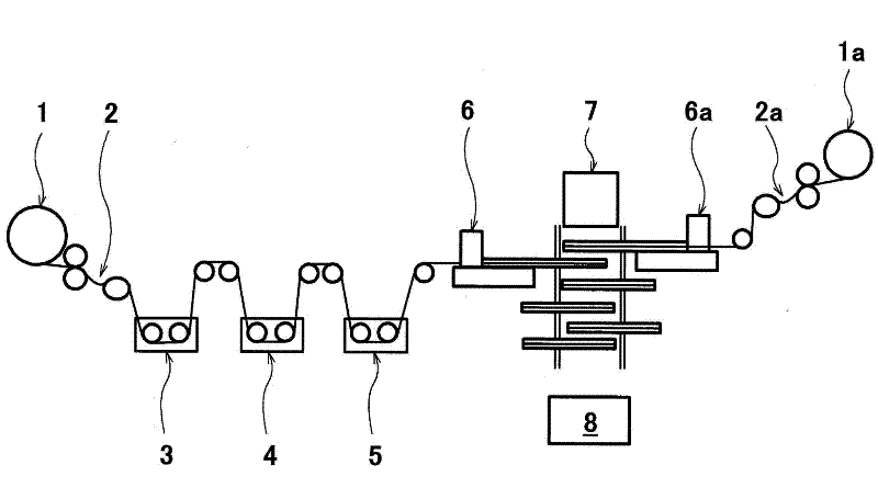
[0128] (1) Fiber battery manufacturing equipment

[0129] figure 1 It is a schematic configuration diagram showing an example of a fiber battery manufacturing facility. figure 1 Reference numeral 1 in the middle indicates a winding roll for winding a fiber bundle of a plurality of polyacrylonitrile (PAN)-based carbon fibers into a roll shape. Reference numeral 2 denotes a fiber-opening device for opening a carbon fiber block formed of a fiber bundle of a plurality of fibers and preparing it for use in the next step. Symbol 3 represents the plating tank; symbol 4 represents the electrolytic tank; symbol 5 represents the alkali tank. Symbol 6 represents a device for forming a separator coating; symbol 7 represents a pressure cutting device for laminating, compression molding and cutting a fiber positive electrode and a fiber negative electrode having a separator coating formed on at least one of them; symbol 8 represents a positive electrode terminal and the negative terminal...

Embodiment 2

[0136] image 3 It is a schematic structural diagram of another example of fiber electrode manufacturing equipment. By using such as image 3 The advanced fiber electrode manufacturing equipment has produced fibrous nickel hydroxide positive electrodes for alkaline secondary batteries. exist image 3 In , reference numeral 31 denotes a winding roll for winding a fiber bundle of 12,000 PAN-based carbon fibers into a roll shape. The fiber bundle of the PAN-based carbon fiber 32 rewound by the winding roller 31 passes the upper and lower paired guide rollers 33a and 33b, and blows the pressurized air 34 compressed by the air compressor (not shown) to open the fiber. The bundle is opened from the original 1cm wide to 5cm wide. Reference numerals 35a and 35b denote diffusers for dispersing pressurized air in the width direction of the carbon fiber bundles. The diffuser plates 35a and 35b have the same function as the diffuser plates 15a and 15b.

[0137] The opened PAN-based ...

Embodiment 3

[0144] Figure 4 It is a schematic structural diagram of another example of fiber electrode manufacturing equipment. can be obtained by using such as Figure 4 Advanced fiber electrode manufacturing equipment to produce fibrous positive electrodes for lithium-ion secondary batteries. exist Figure 4 In , reference numeral 71 denotes a winding roll for winding a fiber bundle of 12,000 PAN-based carbon fibers into a roll shape. The fiber bundle of the PAN carbon fiber 72 rewound by the winding roller 71 passes through the upper and lower paired guide rollers 73a and 73b, and blows the pressurized air 74 compressed by the air compressor (not shown) to it, from the original 1cm wide The fiber opening is 5cm wide. Reference numerals 75a and 75b denote diffusers for dispersing pressurized air in the width direction of the carbon fiber bundles. The diffuser plates 75a and 75b have the same function as the diffuser plates 15a and 15b.

[0145] The opened PAN-based carbon fibers ...


PUM

PropertyMeasurementUnit
thicknessaaaaaaaaaa
thicknessaaaaaaaaaa

Abstract

Disclosed is a method for efficiently producing a plurality of fiber electrodes simultaneously from a plurality of fibers, which takes advantage of the advantages that fiber electrodes conventionally have. The method for producing fiber electrodes has steps (2,2a) for opening a bundle of fibrous material, steps (3,4,5) for obtaining a fiber cathode or a fiber anode by means of forming a cathode active material coat layer or an anode active material coat layer on each monofilament obtained by means of opening, and steps (6,6a) for forming a separator coat layer on the abovementioned fiber cathode or fiber anode.

Description

Technical field [0001] The invention involves fiber electrodes suitable for batteries or capacitors and its fiber batteries, as well as manufacturing equipment for the fiber electrode and fiber battery.The fiber battery of the present invention can be suitable for secondary batteries with aquatic solution as an electrolyte, specifically nickel-hydrogen battery or nickel-cadmium-cadmium battery, nickel-iron battery, nickel-zinc battery, or lead battery.The fiber battery of the present invention can also be suitable for non -hydrolytic secondary batteries, air batteries or capacitors represented by lithium ion batteries. Background technique [0002] The existing aquatic solution is used as a secondary battery of the electrolyte, with positive plates, partitions, and negative plates.Alkaline secondary batteries usually use harsh potassium or water solution of lithium hydroxide to dissolve as electrolytic solution; lead battery is usually used as electrolytic solution as electrolyti...

Claims


Application Information

Patent Timeline
Patent Type & Authority Applications(China)
IPC IPC(8): H01M4/139H01M2/10H01M2/16H01M2/26H01M4/02H01M4/04H01M4/13H01M4/24H01M4/26H01M4/66H01M4/75H01M10/04H01M10/058H01M10/28H01M50/209
CPCH01G11/26H01M4/0409H01M2/0217H01M2/1061H01M10/0413H01M4/139H01M4/75H01M4/0404H01G11/40H01G11/50H01M4/1391H01M4/70Y02E60/122Y02E60/13H01M4/66H01M6/46H01M4/1397Y02E60/10H01M50/103H01M50/209Y02P70/50H01M10/058H01M10/0525H01M2004/022H01M50/547H01M10/0468
Inventor 堤香津雄西村和也高崎智昭名小路昌辉境哲男齐藤诚姚金翰向井孝志
Owner KAWASAKI HEAVY IND LTD
Why Eureka
Try Eureka