Microfluidic chip capable of being used for enzyme-linked immunoassay

An ELISA and microfluidic chip technology, which is applied to laboratory containers, chemical instruments and methods, laboratory utensils, etc., can solve the problems of high background value, expensive, complex ELISA equipment, etc., and achieve low consumption Effect

Inactive Publication Date: 2012-06-20
PEKING UNIV
View PDF0 Cites 10 Cited by
  • Summary
  • Abstract
  • Description
  • Claims
  • Application Information

AI Technical Summary

Problems solved by technology

[0005] The purpose of the present invention is to solve the problems of complex, expensive, high background value, large CV value between groups and other groups based on the microfluidic chip in the prior art, and to provide a cheap, easy to prepare and suitable for high-level Microfluidic chip for high-throughput, high-efficiency, and fast ELISA experiments

Method used


Image

  • Microfluidic chip capable of being used for enzyme-linked immunoassay
  • Microfluidic chip capable of being used for enzyme-linked immunoassay
  • Microfluidic chip capable of being used for enzyme-linked immunoassay

Examples


preparation example Construction

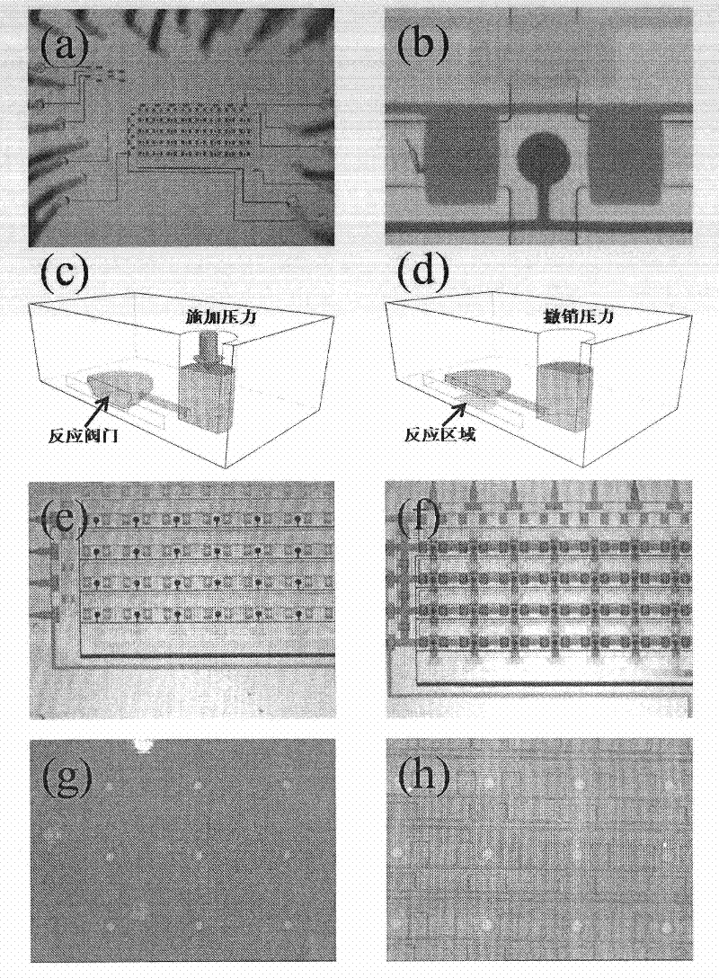
[0029] The following examples illustrate the preparation method of microfluidic chips. In the following examples, relatively simple photoresist SU-8, AZP 4620 and PDMS (Sylgard 184) are used to prepare, but it does not mean that microfluidic chips can only be prepared by this method. Those skilled in the art can understand that any existing technology in the art can be used to prepare the microfluidic chip with the structure of the present invention.

[0030] We first use the method of photolithography to make the templates of the fluid layer pipeline (ie, the microfluidic channel) and the control layer pipeline (ie, the control channel). The control layer pipeline is made of negative glue SU8-2010. Pour negative glue SU8-2010 onto a clean silicon wafer, rotate at 1000rpm for 1 minute, bake on a heating plate at 65 degrees for 5 minutes, bake on a heating plate at 95 degrees for 10 minutes, expose, repeat baking on a heating plate at 65 degrees for 5 minutes, Bake on a heatin...

Embodiment 1

[0033] Structure of the microfluidic chip. This embodiment describes in detail a preferred structure of the microfluidic chip of the present invention, the structure is as figure 1 shown. The microfluidic layer of the chip has 4 horizontal microfluidic channels and 8 vertical microfluidic channels, which intersect with each other to form a 4×8 checkerboard matrix. The 32 reaction valves at the 32 intersections correspond to 32 ELISA At the reaction site, there are four control valves around each reaction valve, which control the four-direction microfluidic channels connected to the reaction site. On the horizontal microfluidic channel, a set of 2 control valves to form a smaller closed reaction space around the reaction site perimeter, so there are 80 such control valves in total. The microfluidic channel communicates with the external connection through several pipes, some of which are used to inject liquid into the microfluidic channel, and the rest of the pipes are used t...

Embodiment 2

[0035] The specific test operation process.

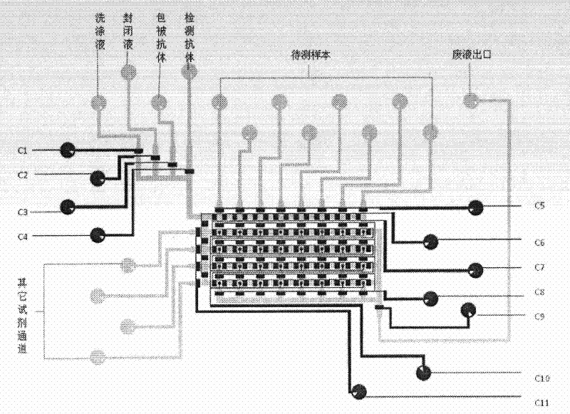
[0036] figure 2 A schematic of the microfluidic chip design is shown. The operation process of the ELISA test will be described in detail below in conjunction with the chip design diagram.

[0037] Chip structure such as figure 2 shown. In the actual microfluidic chip immunoassay, 11 valves (corresponding to figure 2 C1-C11) control the injection of different reagents, as well as the flow direction of the liquid. The round black valves are reaction valves and the rectangular black valves are control valves. The functions of C1-C11 valves are as follows: C1, C2, C3, and C4 valves respectively control the injection of washing liquid (PBS), blocking buffer (Blocking Buffer), coating antibody (CapAb), and detection antibody (DetAb); C5 valve Control the injection of eight gradient parallel channels (sample to be tested); C6 valve protects the entire chip; C7 valve controls the flow of liquid along the longitudinal parallel pip...


PUM


Abstract

The invention relates to a microfluidic chip capable of being used for enzyme-linked immunoassay (ELISA) which is low in cost and easy to prepare. The microfluidic chip comprises a microfluidic layer, a control layer and a connecting layer for connecting the microfluidic layer with the control layer, wherein a microfluidic passage in the microfluidic layer and a control passage in the control layer have at least one overlap point; the connecting layer at the position of the overlap point is made of an elastomer material; when pressure in the control passage is increased to a certain value, the elastomer connecting layer at the position of the at least one overlap point will expand towards the microfluidic layer and is in contact with the inner surface of the microfluidic passage to form a contact surface of a certain size; the width of the contact surface formed on at least one part of overlap points is less than that of the microfluidic passage at the overlap point, so that the microfluidic passage is in a communication state; and when the pressure in the control passage is restored, the elastomer connecting layer at the position of the overlap point is restored to the original state. Through the structure, an ELISA reaction region can be conveniently formed in the chip, so that the ELISA is quickly performed.

Description

technical field [0001] The invention relates to a microfluidic chip, in particular to a microfluidic chip which is cheap, easy to prepare and can be used for enzyme-linked immune reaction. Background technique [0002] Enzyme-linked immunoassay (ELISA for short) is a method for detecting antibodies by using the specific bonding characteristics between antigens and antibodies. Since the 1960s, this immunoenzyme technology has been widely used in the fields of biology and medicine to detect important indicators such as antibodies, viruses, hormones, and disease markers in animal serum. Conventional ELISA reactions are implemented on 96-well plates, and each step in the analysis requires washing and mixing. This technique has disadvantages such as long reaction time, inhomogeneous sample handling, and high reagent consumption. Based on these problems, the researchers introduced the new technology of microfluidic chip. The principle is to transfer the functions of the analysis...

Claims


Application Information

Patent Timeline
Patent Type & Authority Applications(China)
IPC IPC(8): B01L3/00G01N33/53
Inventor 黄岩谊郑春红王静雯庞玉宏王建斌
Owner PEKING UNIV
Why Eureka
Try Eureka