Method and device for detecting pressure of laser shock wave

A technology of laser shock and shock wave, applied in the direction of measuring devices, force/torque/work measuring instruments, instruments, etc., can solve the problems of increased measurement cost, damage of measuring devices, high equipment requirements, etc., and achieves convenient operation, simple device and low cost Effect

Inactive Publication Date: 2012-06-27
JIANGSU UNIV
View PDF4 Cites 9 Cited by
  • Summary
  • Abstract
  • Description
  • Claims
  • Application Information

AI Technical Summary

Problems solved by technology

In 1998, this technology was rated as one of the 100 most important advanced technologies in the United States by the American R & D magazine; in the high-frequency fatigue research program of aero-engines started in the late 1990s in the United States, the laser shock strengthening technology was listed as the first technological measure. In 2005, MIC company, which developed the laser shock strengthening system, won the highest achievement award of the US defense manufacturing. The US listed this technology as one of the key technologies of the fourth-generation fighter engine, which shows the great value of this technology. Research at home and abroad shows that, Laser shock strengthening has a good strengthening effect on various aluminum alloys, nickel-based alloys, stainless steel, titanium alloys, cast iron and powder metallurgy. In addition to having excellent application prospects in the aviation industry, it also has excellent application prospects in automobile manufacturing, medical and health, and marine industries. Transportation and nuclear industry have potential application value; therefore, accurate measurement of laser shock force is of great significance for the application and development of laser shock strengthening. The current method of measuring laser shock is mainly measured by laser pressure sensor , commonly used are: optical fiber pressure sensor, PVDF, broadband loudspeaker, PVDF or PZT transducer, quartz sensor, sapphire sensor, manganese copper wire piezoresistive sensor and optical fiber sensor based on birefringence theory, etc. The equipment requirements are high and the operation is complicated, and the impact of the target on the equipment after the laser shock acts on the target cannot be avoided
The measurement device will be damaged after repeated tests, which increases the measurement cost

Method used


Image

  • Method and device for detecting pressure of laser shock wave
  • Method and device for detecting pressure of laser shock wave
  • Method and device for detecting pressure of laser shock wave

Examples


Embodiment 2

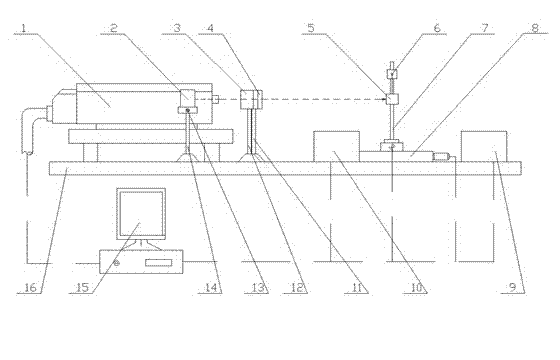
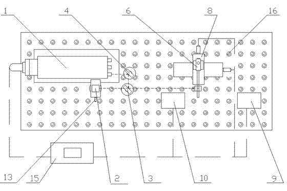
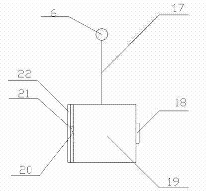
[0033] Using the principle and device of the present invention to carry out a single point on 2024 aluminum alloy, using the PVDF strain gauge 20 and the oscilloscope 10 to measure the laser shock wave pressure action time is 15 μs, and the angle measuring instrument 9 and the acceleration sensor 18 measure the pendulum swing angle to be 16.60° According to the law of energy conservation and momentum theorem, the average force during the laser shock wave action is 7878.37N, and the pressure calculation formula is 1.11GPa.

[0034] The specific experimental conditions are: the length of the thin metal wire 17 is 15 cm, the total mass of the pendulum 5 (sample, PVDF and acceleration sensor) is 337.5 grams, Gaia-R series high-energy pulsed lamp-pumped YAG laser, laser energy 1J, shock The spot diameter is 3mm, the laser wavelength is 1064nm, and the pulse width is 10ns. According to the relationship between laser energy and power density, the corresponding laser power densit...


PUM


Abstract

The invention relates to the field of measuring the mechanics parameter of laser shock, in particular to a method and a device for measuring the laser shock force by use of a pendulum bob. In the invention, the magnitude of the laser shock force is calculated according to the swinging angle of the pendulum bob after the pendulum bob is shocked by laser and the acting time of the laser shock based on the momentum theorem and the conservation law of mechanical energy. The method and device provided by the invention are based on the momentum theorem and the conservation law of mechanical energy, and thus the measurement principle is clear; and the equipment measuring the shock force by use of the pendulum bob has a simple structure and low cost, and is convenient to operate.

Description

technical field [0001] The invention relates to the field of mechanical parameter measurement of laser shock, in particular to a method and device for measuring laser shock force by using a pendulum. It utilizes the momentum theorem, the law of conservation of mechanical energy, and according to the dynamic angle and The laser impact time is used to calculate the laser impact force. technical background [0002] With the development of the aerospace industry, the requirements for the strength of metal parts are becoming higher and higher. The new technology of using strong laser-induced shock waves to strengthen the metal surface is called laser shock strengthening technology (LSP for short). Because of its good surface strengthening effect, It has received extensive attention and research since its inception. In 1998, this technology was rated as one of the 100 most important advanced technologies in the United States by the American R & D magazine; in the high-frequency f...

Claims


Application Information

Patent Timeline
Patent Type & Authority Applications(China)
IPC IPC(8): G01L5/00
Inventor 冯爱新卢轶曹宇鹏聂贵锋杨润谢勇
Owner JIANGSU UNIV
Why Eureka
Try Eureka