Power factor correction (PFC) conversion control method for low output voltage ripple and device thereof
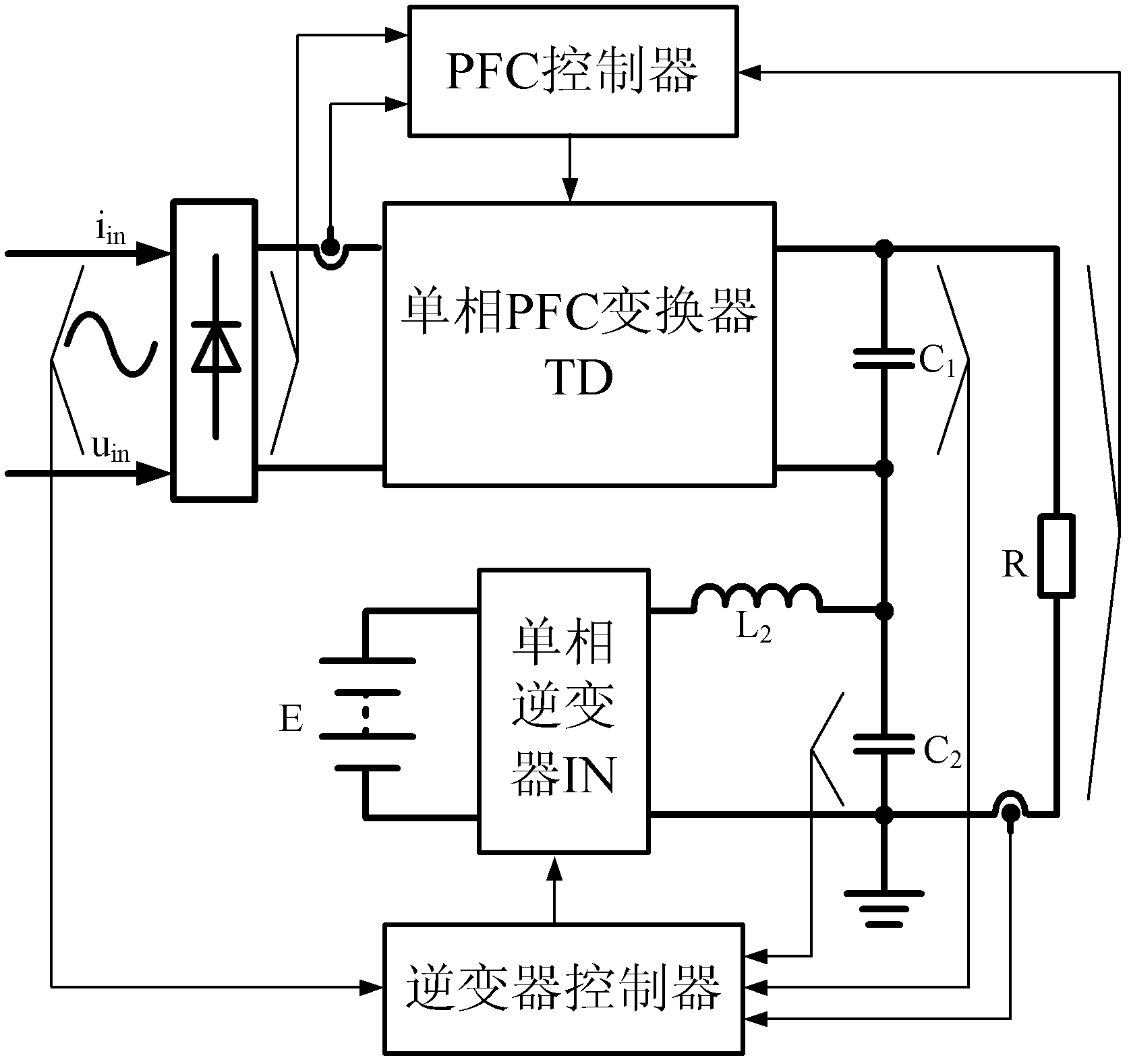
A technology of power factor correction and low output voltage, which is applied in the field of PFC converter working methods and devices, can solve the problems of large DC output voltage ripple, low efficiency, and high cost of converter design, and reduce the DC output voltage ripple. Wave, improve efficiency, improve the effect of cut-off frequency
- Summary
- Abstract
- Description
- Claims
- Application Information
AI Technical Summary
Problems solved by technology
Method used
Image
Examples
Embodiment 1
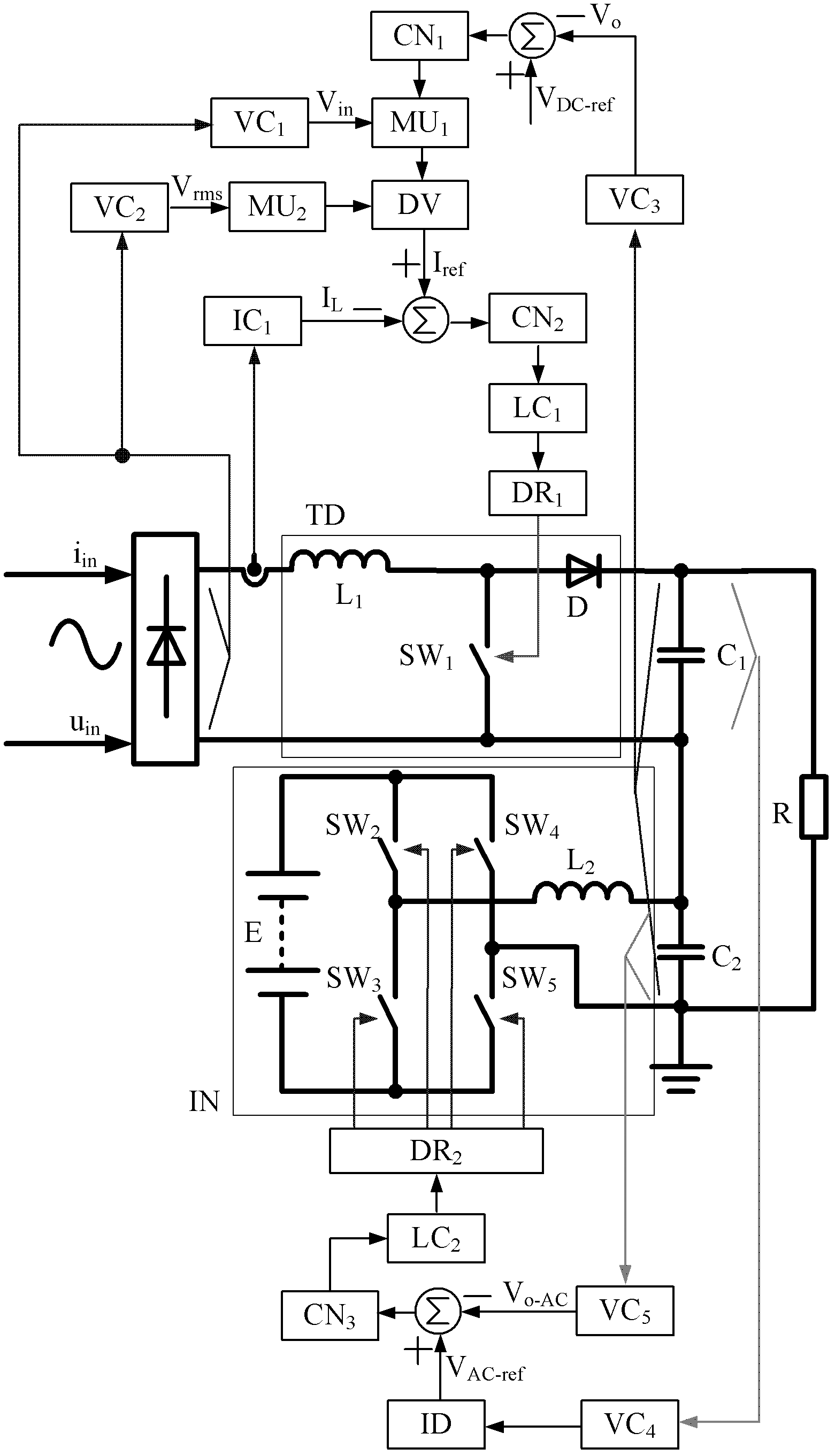
[0054] figure 2 It is shown that a specific embodiment of the present invention is a control method of a switching power supply, and its specific method is:
[0055] Input voltage detection circuit VC 1 Detect the rectified input voltage V of the single-phase Boost PFC converter in , input voltage RMS detection circuit VC 2 Detect the effective value of the rectified input voltage V of the single-phase Boost PFC converter rms , the output voltage detection circuit VC 3 Detect the DC output voltage V of the load R o , the inductor current sense circuit IC 1 Detection of single-phase Boost PFC converter inductor current I L . DC output voltage V o Send error amplifier VA 1 , error amplifier VA 1 With a DC reference voltage V DC-ref vs. DC output voltage V 0 Comparing produces an error voltage value ΔV DC ;Error voltage value ΔV DC Compensation Network CN 1 regulation is then multiplied by the rectified output voltage V in As an input to the divider, the divider di...
Embodiment 2
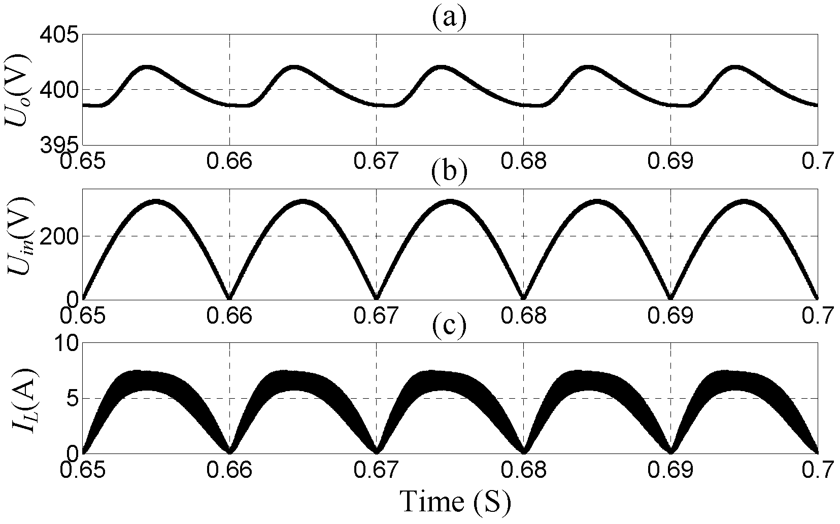
[0074] Figure 15 It is shown that, compared with Embodiment 1, this example differs in that: the output voltage of the single-phase Boost PFC converter is sampled, and the output voltage ripple of the single-phase Boost PFC converter is obtained after the DC blocking circuit ID is blocked, and This is used as the control reference signal voltage V of the single-phase full-bridge inverter AC-ref . The control mode and working process are similar to the first embodiment. It can also be proved by simulation results that it can realize the object of the present invention.
Embodiment 3
[0076] Figure 16 As shown, the difference between this example and the first example is that the PFC converter of the switching power supply is an isolated Boost converter. The control mode and working process are similar to the first embodiment. It can also be proved by simulation results that it can realize the object of the present invention.
[0077] The inventive method can also be used for Buck converter, Cuk converter, forward converter, flyback converter, half-bridge converter, full-bridge converter except the switching power supply that can be used for the Boost PFC converter in the above embodiment. The PFC switching power supply composed of various power circuits such as converter, bridgeless PFC converter, isolated PFC converter, etc., its control strategy is in addition to the average current control strategy of the Boost PFC converter in the above embodiments, and peak current control, Single-cycle control and other PFC converter control strategies. In additi...
PUM
 Abstract
Description
Claims
Application Information
 - R&D
- Intellectual Property
- Life Sciences
- Materials
- Tech Scout
- Unparalleled Data Quality
- Higher Quality Content
- 60% Fewer Hallucinations
Browse by: Latest US Patents, China's latest patents, Technical Efficacy Thesaurus, Application Domain, Technology Topic, Popular Technical Reports.
© 2025 PatSnap. All rights reserved.Legal|Privacy policy|Modern Slavery Act Transparency Statement|Sitemap|About US| Contact US: help@patsnap.com


